August 1, 2008
Restoration
2 Comments
Restoring the antique fan also involved some safety upgrades. Along the way, I derived the schematic. The motor has three connecting wires, but the trick was to figure out how the wires connected to the motor windings.
I measured the resistance between each wire, assigning the wires the arbitrary designators A, B, and C. The resistance between A and B is 53.3 ohms, B and C: 35.3 ohms, and A and C: 19.1 ohms. Assuming the star configuration shown in the figure below, it’s possible to calculate R1, R2, and R3 as follows. R1 + R2 = 19.1, R2 + R3 = 53.3, R1 + R3 = 35.3, therefore (solving for R1, R2, and R3 using substitution) R1 = 0.55 ohms, R2 = 18.55 ohms, and R3 = 34.75 ohms. Clearly R1 is just the center tap and R2 and R3 are motor windings.
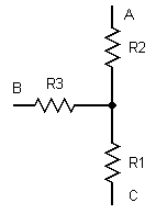
Based on this information and similar measurements performed on the speed coil, the schematic was reproduced as follows:
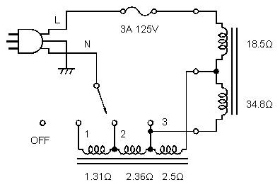
This schematic shows two of the safety upgrades. First, I added a 3-prong AC cable and connected the metal chassis to the safety ground. Then, I added a fuse inline with the AC hot. The fuse serves two purposes: it prevents a fire if the motor windings short, and it also will blow if the AC hot shorts to the chassis.
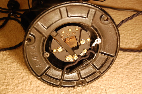
Here’s what the underside looks like without the cover. The switch contacts, the fuse, and part of the speed coil are all visible.
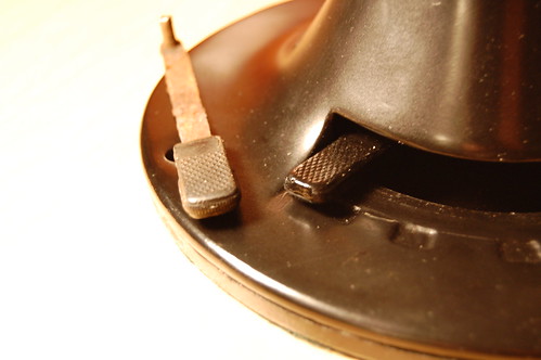
The original speed selector switch lever was metal, which was not very safe because the lever was connected directly to AC hot. Only the plastic knob prevented a nasty shock. I fabricated a new lever out of FR-4 fiberglass sheet. The knob itself was originally molded onto the metal lever and I could not remove it, so I made a new one by casting a replacement out of epoxy.
July 31, 2008
Restoration
8 Comments
At the De Anza Electronics Flea Market, someone was selling a rather beat-up and rusty desk fan. But it was no ordinary desk fan, this one was quite old. I had to have it. Later on, it looked at me plaintively from my workbench.
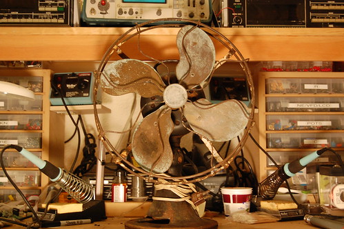
Suddenly it hit me–I had to restore this bedraggled-looking thing!
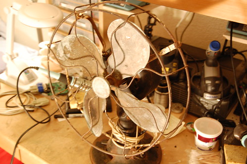
It was a really long and involved process, taking me well over a month, but I have finally (mostly) finished. Why did it take so long? Well, for example, I found that the speed coil (basically a big inductor with taps for each speed setting) was slowly being eaten by rust. Thus began the arduous process of disassembling the entire coil, pulling apart the laminations, polishing off all the rust, varnishing them again (since the laminations must be insulated from each other), and reassembling the whole thing.
All the work really did pay off. Here is what the mostly completed fan looks like. It’s fully operational. The cotton-covered twisted line cord I purchased from Sundial Wire. The plug is actually a standard item at OSH, believe it or not. I guess styles don’t really change much. The cord the fan came with was a more modern zip cord with a quick-plug, and the replacement plug is basically a 3-prong copy of the original.
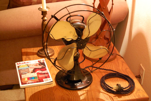
Why “mostly?” Well, the badge that goes in the center of the cage is pretty much beyond repair, and it also appears to be the wrong badge for this fan.
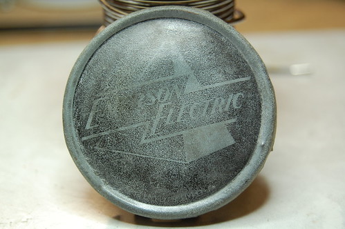
The badge should be brass with a slightly different logo. Regardless of whether or not this badge is original, brass would look a whole lot better. I have been trying (and failing at) various brass etching techniques, since I have the CAD drawing of the logo already.
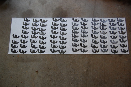
Problem #1 is getting the toner transfer method to work. I have used magazine paper (an old issue of Nuts and Volts: my Make magazine issues deserve better!) and it really does not work for me, probably due to the amount of toner my laser printer puts out. Trust me, I tried a dozen times or so.
Problem #2 is the actual etching process. Salt tank etching was a bit too faint, so next time I will try ferric chloride, which is usually used for PC boards, but should work for brass as well.
Problem #3 is getting the etched brass sheet into the proper shape, which is convex in the middle with a rounded rim. Metal tabs in the back fold around the disc in the center of the cage to hold the badge in place.
If you have any ideas, drop me a line in the comments…
July 31, 2008
Restoration
No Comments
Previously I posted about a vintage Clough-Brengle oscillograph I obtained. It’s been a long process, but I’ve restored it to operational condition.
One of the first steps in the process was to figure out what needed to be fixed. In electronics this old, the first thing I check are the capacitors. They were mostly paper capacitors which I just replace outright since they usually fail.
For this restoration project, I want to keep the vintage look as best as possible. One way is to dress up the new capacitors in the clothes of the old capacitors.
In this picture you can see the metal cans containing the old capacitors and the new ones soldered on top for testing purposes.
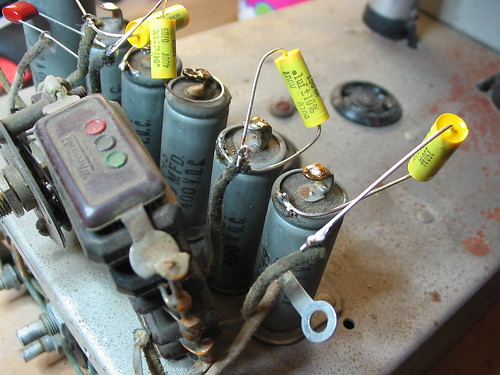
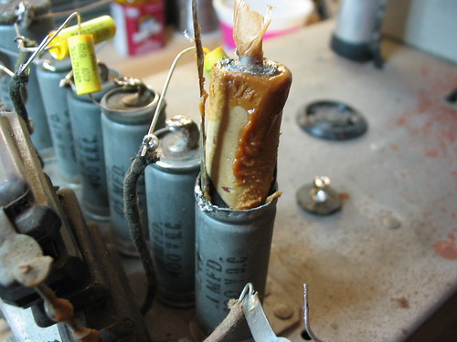
Here I have used pliers to bend the flange back and remove the “lid.” The stuff inside is a wax that insulates and holds the actual capacitor roll in place.
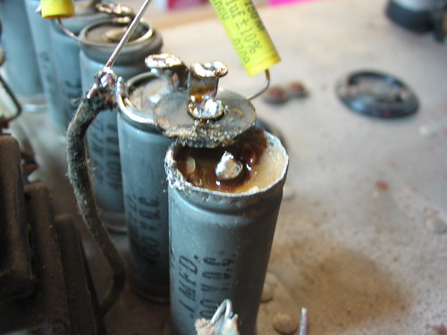
The easiest way to remove it was to put a big wood screw right in and pull it out with pliers.
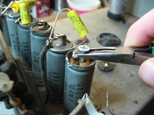
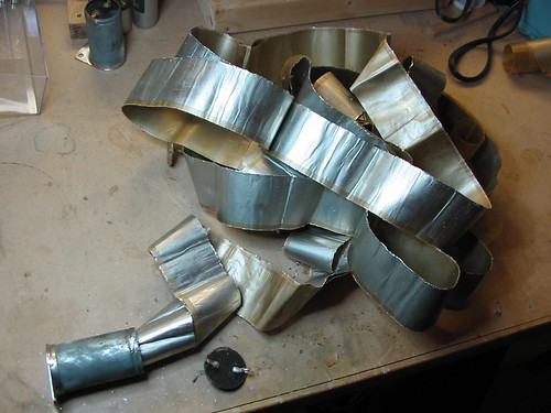
Now you can see what the roll itself looks like. It’s actually Kraft paper (like a very thin version of grocery bag paper) that has been vacuum deposited with an aluminum film. Two sheets are rolled up together producing the capacitor. The Kraft paper is impregnated with oil to increase the dielectric strength.
Here’s a larger one that I unrolled all across my workbench.
Notice how much smaller the new capacitor is. This fits easily in the metal can that once contained the old capacitor.
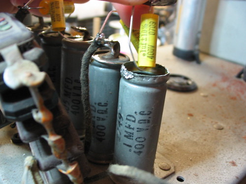
It was difficult to close the rolled metal lip without denting it, so it doesn’t quite look like the original, but it still beats ripping out the old capacitor or having the new capacitor squat on top like some sort of parasitic insect.
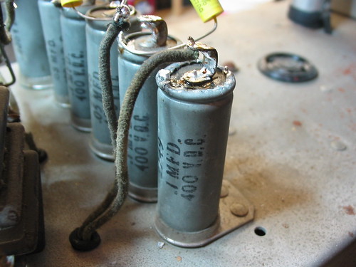
After recapping everything, it was time to strip down the chassis and get rid of the rust. I got rid of most of it, although there was a lot of pitting and such left over. I used Naval Jelly which does a good job of converting the original iron oxide (ugly red rust that spreads like gangrene) to iron phosphate (which pretty much just sits there). The grommets had all hardened and were crumbling off, so I replaced those as well.
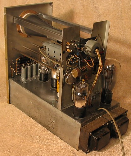
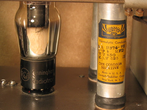
Here’s a closeup of the back. You can see a few cardboard-roll style capacitors which have actually been gutted and fitted with shiny new capacitors on the inside. I sealed the ends using the old wax. Speaking of capacitors, I also had to replace two big electrolytic filter capacitors. The insides were filled with hardened pitch which I had to drill out to make room for the new capacitors, which were about 1/10th the size. Don’t you like the label?
This thing runs great now. I even dragged it out to the Maker Faire, but I didn’t plug it in for fear of wandering fingers (I left the cover off to expose the excellence inside).
