Oscilloscope Video Monitor

Cleverness, Projects 12 Comments

Watch this YouTube video, and then read the rest of the post.

So how did I do it? It is actually a very simple circuit.
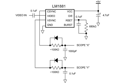
Basic Ramper Schematic

The LM1881 separates the sync signals from the NTSC composite video coming from the camera. It outputs a vertical sync signal (active low) that asserts during the vertical retrace period and a composite sync signal (also active low) that asserts during the horizontal retrace period and also during the vertical retrace period (but with a set of serration and equalization pulses).

To connect these to my oscilloscope, I have to use the XY mode on the scope and convert the sync signals into deflection signals. This is done using analog ramp generators. The simplest way is to use an RC circuit to generate a rather nonlinear ramp. When the sync signal goes high, it charges the capacitor through the resistor. When the sync signal goes low, the diode allows the capacitor to discharge immediately. This generates the sawtooth waveform. Adjust the R value so you get the most complete ramp (goes most of the way up to 5V).

The video signal is fed directly into the Z-axis signal at the back of the scope. Because the Z-axis signal has the opposite polarity from regular video (it is a blanking signal, where a positive voltage will turn the beam off), I had to build a really basic video buffer to invert the signal. This is a nice exercise in transistor biasing using four external resistors. Don’t ask me for the schematic–you should try to build it yourself. Even if you don’t get it working properly right away, you’ll discover all sorts of interesting analog video effects!
555 Contest Entry

Projects 27 Comments

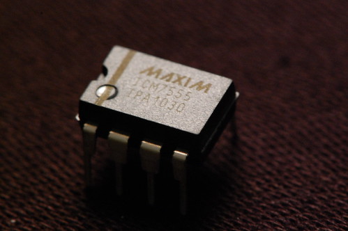
Yes, it’s not really vacuum tube related, but I built an entry for the 555 timer contest. It uses an ICM7555, which is Maxim’s second source of Intersil’s CMOS version of Signetic’s original NE555 timer. Turns out the fact that it is CMOS is important for this particular circuit…

ICM7555 - CMOS Timer IC

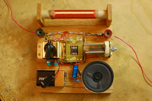
My entry is an AM radio. The only active device (silicon, germanium, or otherwise) is the ICM7555. The tuning is accomplished with an inductor and a capacitor, and the ICM7555 acts as an AM demodulator and class-D power amplifier to drive the speaker.

555 Radio

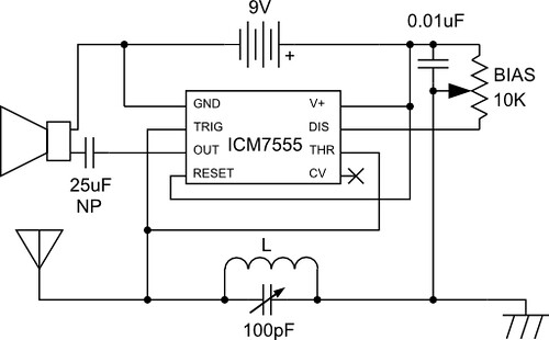
You may be wondering how all this is accomplished with a 555. The schematic is below.

555 Radio - Schematic

Here’s how the circuit works: The AM radio signal is tuned by inductor L, which is 300 turns of wire on a 1/2 inch diameter cardboard tube made out of an old toilet paper roll, along with the 100pF variable capacitor. One end of the parallel configuration of L and C connects to an antenna (surprisingly long!) and the other end connects to a ground wire which is tied to the AC outlet ground (old books tell you to ground it to a water pipe). So far this is exactly like an AM crystal radio.

The 555 timer is configured as a pulse width modulator in a non-traditional configuration. If I used the standard approach and connected the input to the CV pin, the low impedance of the pin would prevent the circuit from receiving any radio signals. I had to invert the circuit and tie both high impedance analog pins, Threshold and Trigger to the radio signal input. This is the reason why the CMOS version of the 555 timer performs much better than the standard bipolar, which has higher input bias current.

The pulse width modulator ramp is created by the 0.01uF capacitor and the 10K bias potentiometer which are connected to the Discharge pin. The potentiometer wiper goes to the LC arrangement. With no radio signal coming in, the voltage on Threshold/Trigger ramps up until it hits the threshold, and then Discharge causes the voltage to ramp down again.

When a radio signal comes in, it gets superimposed on the ramp signal, causing the threshold and trigger comparators to trip early or late in a cycle. This variation causes the output duty cycle to vary, which we can hear as sound in the speaker.

Demodulating the signal properly requires adjustment of the bias knob, so that part of the radio signal is “clipped” and ignored by either the threshold or trigger comparators. This ensures that the negative “halves” of the radio wave don’t cancel out the positive “halves”.

Want to hear what it sounds like? Check out the video below:

And of course, I can’t end the post without a gratuitous shot of the ICM7555 in circuit.
555 Radio - The Core

Steampunk Wristwatch

Clocks, Projects 5 Comments

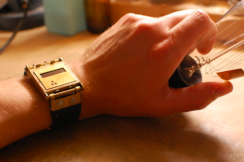
Steampunk Wristwatch
Is that…?
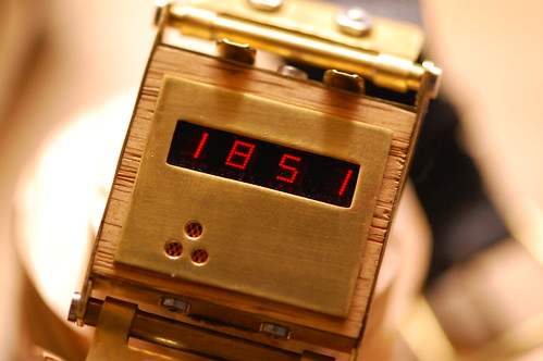
Steampunk Wristwatch
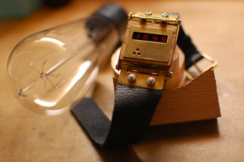
Yes, it’s an LED steampunk wristwatch! It uses the LED wristwatch board (see this previous post). The watch is constructed from a small piece of oak and pieces of brass sheet and tubing. I used hand tools, a Dremel tool and a cordless drill to shape and form each of the pieces.

There are four more LED wristwatch boards left. I wonder what style of watch I should make next…

Here’s one more picture.
Steampunk Wristwatch

LED Wristwatch

Clocks, Projects 12 Comments

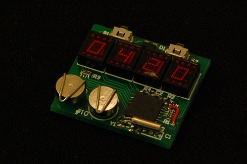
Sure, this doesn’t use a vacuum tube, but it’s still a neat way to reuse some old-fashioned 7-segment LED displays. OK, so I can’t wear it yet. It still needs a case and watch band. I am kicking around a few ideas, but feel free to post a comment if you have any suggestions.
LED Wristwatch
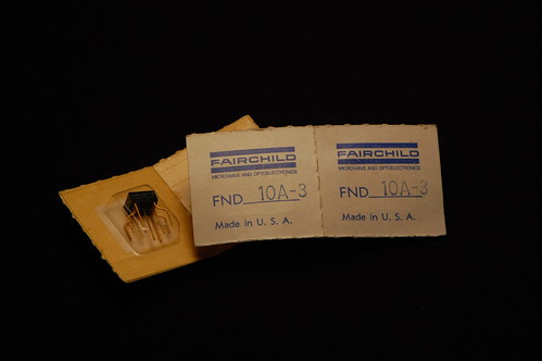
The LED displays are quite tiny and would have been used for calculators or similar devices back in the day. They were made by Fairchild as you can see by the original packaging:
LED Wristwatch - Fairchild LED Chips
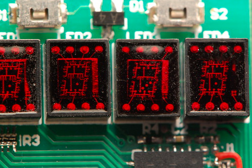
The unique thing is that each display has a single die inside with each of the segments etched into it. In the picture below, you get a pretty clear look at the bond wires and the top metal layer. If you click the image, I have annotated the Flickr page.
LED Wristwatch - Closeup of LEDs

Back to the watch. It keeps the time with a fairly pedestrian PIC16F628A. It has an internal timer that operates with a separate oscillator (which is the watch crystal in the lower right corner) which can run even during sleep mode. This is critical to keeping the power consumption low. When a timer tick occurs, it generates a wakeup event, and the processor can increment the internal timekeeping registers. The processor can also wake up when one of the buttons is pressed. When that happens, it turns on and starts multiplexing the LEDs so that it can display the time. After a short delay it goes back into sleep mode. I haven’t yet calculated or tested the battery life.

The batteries are ZnAir number 10 (a common hearing aid battery). This is a zinc-air cell that uses oxygen as part of the electrochemical reaction, which is why there is a tiny hole in the top of each cell. Any battery holder has to allow air to make contact with the hole. In many states, these are the only batteries you’re allowed to throw away in the regular garbage. California is one of the exceptions, and the state considers zinc to be hazardous waste, so these batteries have to be collected separately in a category called “universal waste”. To me this seems foolish because I suspect that a lot more zinc is released into landfills as bits of scrap galvanized metal. Things like galvanized flashing, nails, and deck screws. Regardless of legislation, zinc is a lot less harmful than lithium, so remember to dispose of your burned-out LED throwies properly (and not in the regular garbage).

Here’s a puzzle for you: the PIC has 13 I/O pins. The LED displays use 8 (7 segments plus 1 decimal point) anodes and 4 cathodes. That leaves a total of 12 I/O pins, and I am not using the 13th I/O pin (RA4) because it is open drain and not useful in this circuit. So how are the two pushbuttons wired to the PIC? In fact, how can either button cause the PIC to wake up from sleep? Post a comment with your theory. I’ll give you one hint: there is a dual diode connected in some fashion to both switches.

And here’s one last photo to give you an idea of how small this thing is:
LED Wristwatch - Coin for Scale

Electroluminescent Display Panel

Projects No Comments

You’ve probably seen LCD displays that use electroluminescent panels for the backlight. They’re not so common since the advent of the white LED, but they were used all the time for those 5×7 character displays. Wikipedia has a nice article about electroluminescent technology.

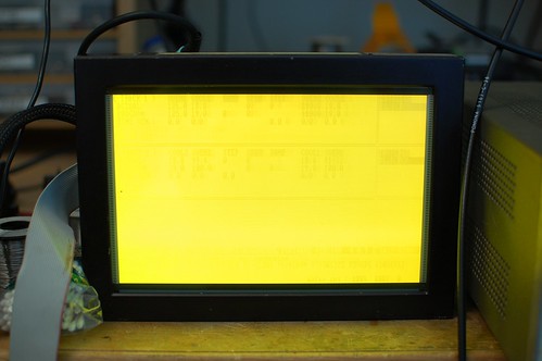
Well, it turns out they can be used to make displays:
EL Display Panel

Here’s a closeup of the pixels:
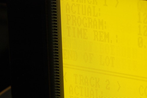
EL Display Panel - Closeup

The “ghostly” numbers are letters are the result of the screen displaying the same thing for years and years. Looks like it was from a machine used for rapid thermal processing of semiconductor wafers.

This display panel was made by Finlux. There’s a very thorough history of this company and EL displays here: http://www.indiana.edu/~hightech/fpd/papers/ELDs.html.

It’ll be fun coming up with a project for this one. The display is 640×200, “high resolution” CGA. The video inputs are TTL-level video, hsync, vsync, and pixel clock. It will probably work at other frequencies too since the panel just uses high-voltage shift registers, not some special video ASIC. The tricky part will be getting the pixel clock to the device since video card connectors don’t provide that. Maybe I’ll just drive it with a microcontroller…

« Previous Entries Next Entries »