April 13, 2009
Projects
No Comments
For another project in progress, I needed to test the “off” leakage current of neon bulbs. Along the way I discovered some interesting things. First, let’s take a look at the test subjects.
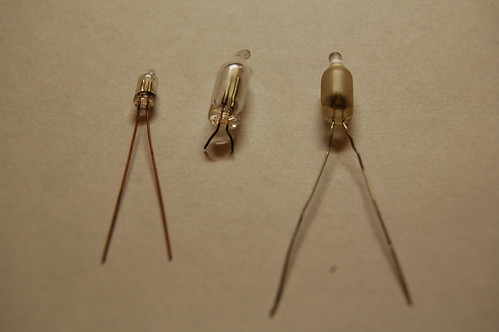
The lamp on the left side is a brand new miniature-type, the middle lamp pretty much represents the average neon lamp, and the lamp on the right is a special “frosted” lamp that I pulled out of some old equipment. Sorry, I do not have type numbers for these lamps, and they are not marked. Some older neon lamps were marked with the type number when the seal was crimped.
The testing used a power supply adjustable from 0V to 40V and a Fluke 87 multimeter. Any good multimeter with a 10MΩ input impedance can be used to measure extremely low currents by wiring the meter in series (like an ammeter) while it is in volts mode. Tests of the tiny neon lamp and the “average” neon lamp used the meter in mV mode, while tests of the frosted lamp used the volts mode. The tests were conducted at room temperature at normal indoor lighting conditions. Before testing, each lamp was washed with 90% isopropyl alcohol and dried with canned air.
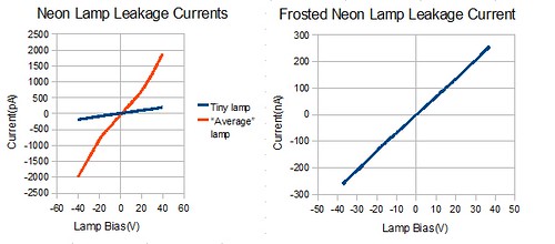
There are some very interesting observations to be made with this data. The tiny lamp exhibits very low leakage current, peaking at 200pA. The “average” neon lamp peaks at 2nA, and the frosted lamp peaks at 263nA. I tried a few more lamps of each type and although they vary quite a bit, each type of lamp approximates the same current as the data above. It is due to the construction of the lamps themselves. According to Techlib.com, the increased leakage current is due to the radioactive thorium present in the lamp electrodes.
If it’s possible for radiation to increase the leakage current, I surmised that a strong light source could increase it as well. Taking another “average” neon lamp, I measured a leakage of 2.8nA at 40V. When exposed to a very bright white LED flashlight, the leakage current increased to 11.0nA, and when exposed to an ultraviolet LED flashlight, the leakage current climbed to 16.6nA. It may be that the photons impinging on the electrodes cause electrons to “leap” from the outer electron shell of the metal atoms and drift (due to the electric field between the two electrodes) across to the opposing electrode. This shows up as the increased drift current.
By increasing the temperature of a neon bulb, I was able to increase the leakage current as well. At the same time, I discovered that some small amount of water vapor still remained as a film on the surface of the bulb. For the case of the tiny neon bulb, the leakage current of 200pA fell to 50pA after a few seconds of applied heat, invalidating my previous experiments. As the temperature of the bulb increased, the leakage current increased to 1100pA before I removed the heat. This principle is the same one that enables vacuum tubes to operate–the heated cathode generates a space charge “cloud” of electrons that drift depending on the applied potential.
For my application, I would rather not have any thorium in the lamp since I want the leakage current to be as low as possible.
April 5, 2009
Projects
10 Comments
Recently I completed the construction of a Dekatron-based kitchen timer. A Dekatron is an electronic counting device used in the middle of the 20th century for counting pulses or dividing input pulses. You can find a very good introduction to the devices at Mike’s Electric Stuff. My timer is certainly not the first. This gentleman has created a rather military-looking kitchen timer that uses three Dekatrons.
Dekatrons are relatively difficult to find, so I decided to use a single Dekatron in my timer. Actually this project is an old one that I revisited. The original project was just going to be a spinner, but I had trouble with the driving circuit (it never worked reliably). For the 2008 Maker Fair I dusted it off and tried to power it up–with 12V instead of 5V. The power supply and microcontroller did not appreciate it and the whole thing stopped working. The second time around I decided to turn it into something useful. Here it is.
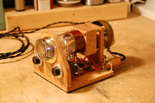
The driving circuit in the Dekatron kitchen timer is based on a circuit drawn up by Mike Moorrees. You can find the circuit at the NEONIXIE-L mailing list files section. There’s a good excuse for you to join. If you’re interested at all in antique display devices (not just Nixie tubes) you need to join.
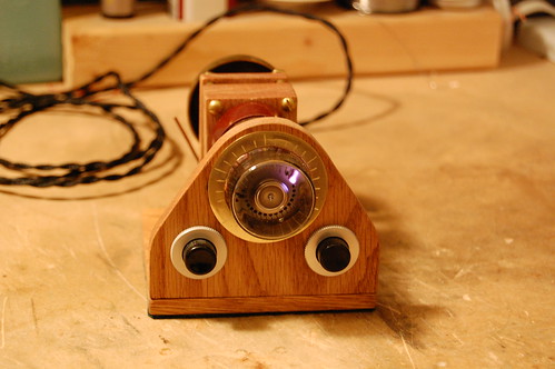
There are twenty minutes remaining on the timer. You can read the time using the scribed lines on the brass ring around the Dekatron. The ionized gas in the tube glows purple because of the high argon content.
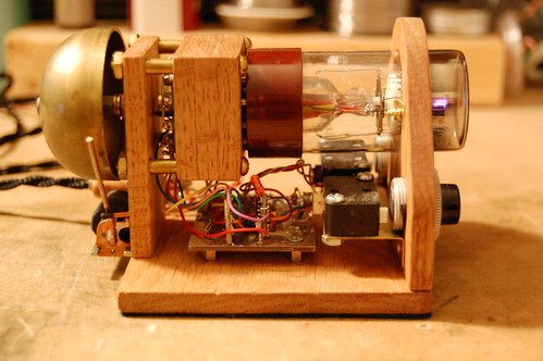
In this side view, you can clearly see the high voltage power supply. It has a copper-wound ferrite toroid. The power supply converts 5V up to 450V by a MAX845 that pulses the transformer at 535KHz, and the 150V output of the transformer gets stepped up to 450V through a 3-stage voltage multiplier.
Time is kept and the clock is controlled by a PIC16F84. The brass bell at the end rings once the timer expires. After ringing the bell, the PIC turns off the high voltage supply and enters sleep mode. Pressing a button wakes up the microcontroller and begins a timing cycle.
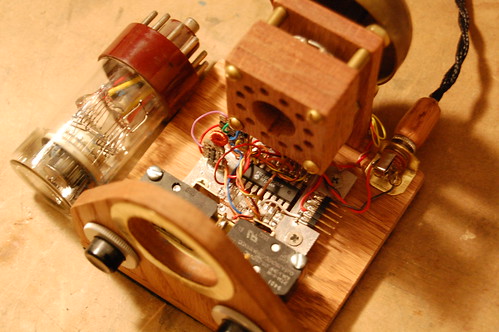
You can see the socket more clearly when the Dekatron is removed. My homebrew drill press for my Dremel tool helped tremendously to drill accurately-placed holes for the pins.
On the right side the power connector provides 5V to the timer from an old cellphone charge adapter. Don’t throw away these adapters! The small ones often contain a very simple off-line isolated power supply that can be modified to produce other output voltages. You can recycle them for projects quite easily. Perhaps I will write an article on this.
The 5-pin connector on the board is used to program the PIC. The PIC16F84 is old enough that it does not support in-circuit debugging. It was Microchip’s very first product on their flash process which has made them so much money over the intervening years.
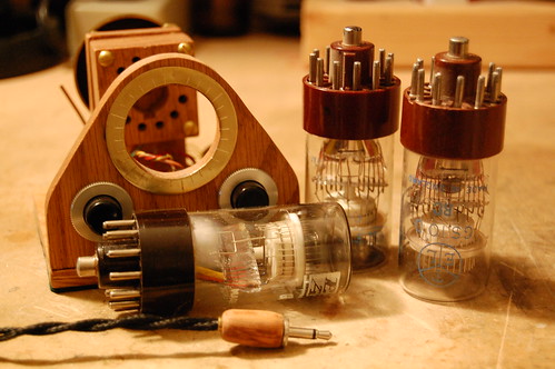
Here is the extent of my Dekatron collection. They are all type GS10D, which is a decimal selector tube with two sets of guide electrodes. The Dekatron in the front of the timer does not work. Can you see why?
February 8, 2009
Projects
No Comments
Here’s a recent product of my workshop. A week of sawing wood, drilling, carving with my Dremel, slicing brass with tin snips, polishing, sanding, and staining resulted in this brand new limited edition (of one) Steampunk timekeeping instrument.
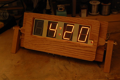
This device is based on the Panaplex clock circuit I built a while back. The displays are seven segment but, like Nixie tubes, are filled with Neon gas. To match them, the colon and PM indicator use small neon lamps.
Construction is stained oak with brass fittings. The device is exactly one inch thick. It can pivot about the two knurled brass nuts on either end.
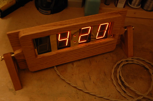
But how does power enter this timekeeping device? It travels through brass terminals (with appropriately colored washers to indicate the polarity) up to the pivot, where it enters the case of the timepiece. Look on the inside edges of the wooden stands, and you will see the polished brass strips that carry the direct current up to the knurled nuts from the terminals.
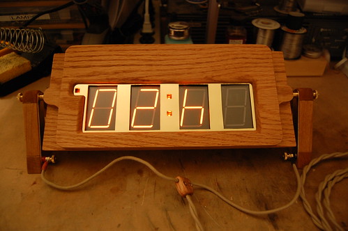
Now for the technical details. The timepiece uses a PIC18F242 running at 4MHz. The time is kept by an exceptionally tiny sliver of quartz imbedded within a miniature silver cylinder–a 32KHz watch crystal. My standard 180V power supply provides the high voltage needed by the Panaplex display elements. Here is the timekeeping instrument with the two halves of the case separated.
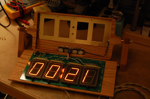
My other designs are usually drawn out in AutoCAD, but this time I decided to use the old fashioned method. The two triangular wooden stands on the end took some tricky geometry. The pivot is exactly 3″ up from the lower edge of the base. The angle of the triangle is 70 degrees, because 60 didn’t look right and 80-90 was too peaky looking.
The switches I found at HSC Electronic’s yearly sale. I like to use unusual looking switches and controls in my projects. I feel very sad when I see someone’s awesome project that has been defiled by cheap-looking Radio Shack switches.
The Steampunk timekeeping device was made using a simple setup of a junior hacksaw (6″ long), an old cordless drill, a Dremel, a Dremel drill press, and numerous small hand tools. Most of the work happened on the back patio of my apartment. Yes, it’s possible to be a Maker even in the big city.
January 7, 2009
Cleverness, Projects
21 Comments
In this previous post I disassembled the Coby DP-151SX digital picture frame. This device is very hackable, and includes a lot of goodies such as a Li-Ion battery and battery charger circuit as well as a neat little color LCD display with a white LED backlight. The pinout for the LCD is in the previous post.
The MAXQ2000 microcontroller development board I have uses a 0.1″ spacing header to connect to the I/O pins, so I made a little adapter and wired it up to the LCD connector using wire-wrap wire. It uses 13 I/O lines, but that could be reduced 11 if CS# is wired to ground and RST# tied to a separate reset IC (such as a MAX811). It’s actually a good idea to use CS#, because you can then multiplex the functionality of all the other pins and recover that I/O.
Here is a picture showing the LCD up and running with a simple test pattern:
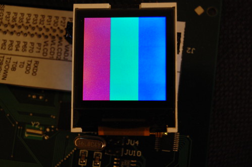
It’s not 128×128, but actually 132×132 pixels. The color depth is 16-bit using a fairly standard 5-6-5 bit encoding. See the PCF8833 datasheet for more details.
Spark Fun has a similar LCD display which uses the same controller, only it costs $20. Amazon.com sells the Coby-151SX in black for $10. Not a bad deal: for $10 less you get a Li-Ion battery, mini-USB cable, and a driver CD, which you could use as a coaster for your Mountain Dew to help with the LCD programming. Spark Fun has some sample code which you should easily be able to adapt for parallel mode (since the Coby LCD connector brings out the parallel data lines, unlike the Spark Fun LCD).
The source code for my test program will get posted once I clean it up and possibly add functionality (Character fonts? Bit blitters?)
January 3, 2009
Projects
1 Comment
Recently I obtained two Coby DP-151SX digital photo keychains to see if it is possible to hack the device. The answer is yes. These devices can be purchased for as low as $9, and I thought they might make a good source of color LCD displays. There is a project to hack small photoframe devices such as these, and they have already developed some tools to hack the firmware and display dynamic images (such as an MP3 player status screen) using the USB connector on the device. The Wiki at the previous link is a good resource.
Below is a photo of the disassembled device. Click the photo to see the Flickr notes annotating different parts of the device.
The specs of the device are as follows:
- LCD: Varitronix COG-C147MVGA, 128×128, chip-on-glass (COG) integrated controller with white LED backlight.
- CPU: Possibly the ST2203U 65C02-compatible device with built-in USB engine.
- FLASH: Spansion S29AL008 1Mx8 NAND FLASH memory.
- Battery: 180mAh 3.7V lithium ion rechargeable.
The ST2203U uses a 65C02 processor core with several peripherals: a DMA engine, FLASH memory controller, real-time clock, LCD controller (not used in the Coby device), and a USB engine. It has an onboard mask ROM, but this appears to be disabled on the Coby device. Since resistor R12 is jumpered with a zero-ohm resistor, the ST2203U boots from the external memory. If R13 was jumpered instead, then the device would boot from the internal memory. Apparently the program that comes with the Coby device has the ability to download new firmware through USB. I’m tempted to write my own firmware for this creature, but the lack of an ICE along with a decent toolchain has deterred me.
The device has a built-in battery charger. I have not yet attempted to reverse engineer it yet. The lack of inductors makes me think it’s a linear charge circuit.
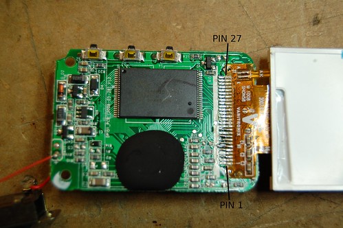
The most interesting part, at least to me, is the LCD screen. It has a built-in controller which appears to be similar to or compatible with the PCF8833. Varitronix, of course, does not provide data on this particular LCD display. Based on a little reverse engineering (since many of the control lines are shared with the memory chip) I was able to figure out a pinout:
- VCC (3.0V, but it probably works at 3.3V too)
- GND
- Unknown. Connected to the COG IC but is not driven as an output. This may be the OTP programming control pin.
- NC (but can be connected to the COG IC with a jumper on the flex cable, J1)
- CS# (Chip Select)
- D/C# (Data/Command)
- RD# (Read)
- WR# (Write)
- RST#
- D0
- NC
- D1
- NC
- D2
- NC
- D3
- NC
- D4
- NC
- D5
- NC
- D6
- NC
- D7
- NC
- LED Cathode
- LED Anode
The next step is to detach the LCD and wire it up to a breakout board. Then I can connect the breakout board to a microcontroller and attempt to communicate with it.
