Laser Printer Scanning Mirror Experiments
August 4, 2008 Projects 18 CommentsDigging through my junk box today, I unearthed the scanning mirror from a laser printer, otherwise known as the Heart of the LaserJet. It’s got the infrared laser that generates the image as well as the scanning mirror that creates the raster. It’d be fun to get it up and running for nefarious purposes…
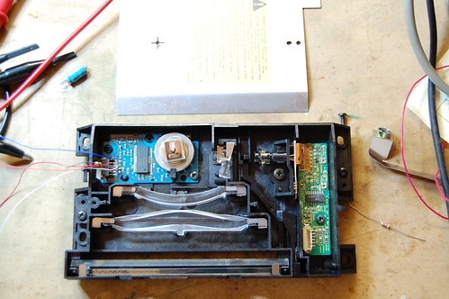
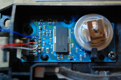
The scanning mirror and motor uses a “custom” (undocumented) Panasonic motor driver, the AN8247SB. As usual, Google returns a million hits for grey market parts brokers who spam the keywords with things like “PDF” and “datasheet” without offering any actual information.
So my usual plan of attack does not succeed.
The second step is to examine the single 5-pin connector to see what I could figure out. Pin 3 is obviously ground because it is the only pin connecting to any large ground planes. What I suspect to be pin 5 appears to be the power supply since it connects to two very low valued resistors (0.75 total) which probably perform a current sense function. Most of the other pins disappear inside the undocumented chip.
Digging around in my junk box produced the power supply board for the laser printer. I was able to find the other side of the connector and quickly verify that pin 3 is indeed ground. What I thought was pin 5 is actually pin 1, and it is indeed power. Tracing back through the power board I notice that it connects to a filter capacitor with a 25V rating. Based on that I conclude that it is very likely a 12V rail. I soldered some jumper wires onto the board and began experimentation in earnest.
Connecting the board to 5V didn’t result in any excessive current, so I slowly ramped up the voltage to 12V. Nothing happened. Not even anything bad.
Looking carefully at the laser printer’s power supply board, I traced the other three connections. They all went into a big microcontroller, but the wiring connections were different. Pin 2 had a 10K pullup to some low voltage supply, pin 4 went straight into the microcontroller, and pin 5 came from an RC filter from the microcontroller.
First I tried connecting a 10K pullup resistor to pin 2 on the motor driver board to 3.3V, and I hung a scope probe on it. It was a logic low. I spun the mirror assembly, and I saw pulses! This must be the tach output. By rotating the mirror very slowly by hand, I counted 6 pulses per revolution.
Next I probed the voltage on the other two pins, which were both weakly pulled up to about 3.6V on the motor driver board. I pulled pin 4 low, and the tiny mirror spun up with a whine to about 13,000 RPM (as measured by the tach output)!
That was really great because I was worried that those two pins were I2C control lines which would have made reverse engineering a lot more difficult. It’s not impossible because you can hook it up to a microcontroller and scan all possible I2C address to see if any slave devices respond, then randomly try to access registers… It gets pretty messy anyway.
The last pin gave me a bit of a headache because grounding it didn’t really do anything. I tried grounding it through an ammeter and noticed that the current, although it started at a few hundred microamps, tapered off quite rapidly. There must be a capacitor in series somewhere on the motor board, and that means the pin is designed for AC signals. Since no signal came out of the pin, it must be an input. I connected a function generator at a few kilohertz with a 3.3Vp-p square wave, and when I turned on the motor, I noticed that it “cogged” a lot and generally had a hard time. On impulse, I dramatically increased the frequency. Suddenly the motor slowed down and settled at a constant speed. By changing the frequency, I could manipulate the motor speed.
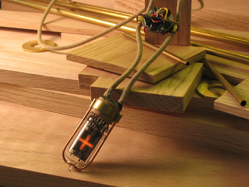
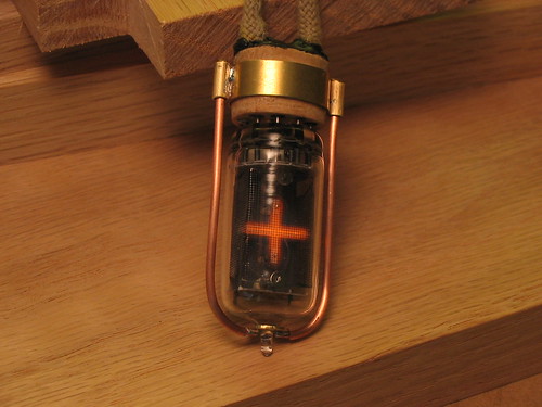
So pin 5 is a synchronization input. I guess the RC filter on the microcontroller side was designed to help reduce EMI in the cable. The next step was to figure out the relationship of input frequency to output speed, so I connected my trusty old Nixie frequency counter to the output of my function generator and my multimeter (set to frequency) to the tach output. The ratio appears to be fixed: divide the input frequency by 136.6 and you’ll arrive at the RPM of the mirror.
Here’s the complete pinout:
1 – +12V
2 – Tach output (open drain, 6 pulses per revolution)
3 – Ground
4 – Enable (active low, so drive it low to turn on the motor)
5 – Synchronization input
Now it’s time to come up with projects…
Just to give you a hint, I have something in mind involving a photomultiplier tube.
Drop me a line in the comments if you think you can guess what my idea is, or to post your own ideas, or even if you find this information useful for your own project.