
Miniature Coin Cell Nixie Tube Power Supply
November 2, 2014 9:32 pm ProjectsUpdate 11/3/2014: Fixed the coil connections on the schematic, along with the inductance. Also, check out this post to see how the circuit works.
This project has been a long time in progress. It started years ago at a Maker Faire where I built a Nixie tube pendant powered by a lithium coin cell battery. Since then, I’ve decided to make a PC board and put together some instructions on how to build such a power supply yourself. These little supplies are great for steampunk jewelry or possibly single-digit Nixie tube clocks (they’re not quite strong enough to drive multiple tubes). The battery life should be around 3 hours or so for a CR2032 lithium coin cell.

The schematic is below–click for a larger view. The bill of materials is located here, including Mouser Electronics part numbers. If you decide to order, get at least 5 of each part just in case you lose or burn up some of them. Note: Mouser seems to be out of stock for the T1 inductor, but Digikey has it here.
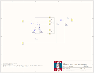
Q1 is a single device; it actually contains two transistors which is why it looks like that on the schematic.
To make it easier to build, I’ve put up a convenient OSH Park project page link so you can order boards. When I ordered from them, it cost $2.80 for a set of three boards (with free USPS shipping). Not a bad deal at all!
When you have boards and components, there’s a specific order of assembly that makes things a bit easier. See this YouTube video:
Basically you need to assemble the components in the following order:
- Solder C1.
- Solder Q1. Be sure you line up the beveled edge with the extra-wide silkscreen. If you put it in backwards the power supply will not work.
- Flip the board over.
- Solder D1, then R2, and then C2. C2 is 0.01uF, similar to C1, but it has a 250V rating. It is very important not to mix these up.
- Solder R1, and then T1 (the big coil, not marked on the silkscreen).
- Take a piece of 32 gauge magnet wire that is 13 inches long and tin about 1/8 of an inch at one end. I use a soldering iron to burn off the varnish. Solder it into the upper left through hole that is below the coil.
- Wrap 5 turns clockwise around the coil T1. Thread the end of the wire into the middle through hole below the coil.
- Turn the wire around and thread it back through the same hole, pulling it tight to form a tiny loop. Solder the loop to the through hole.
- Take the wire and wrap another 5 turns clockwise around the coil. Thread the end through the top right through hole below the coil, and solder it in place. Trim off any excess.
- Get another piece of 32 gauge magnet wire that is 5 inches long, and tin about 1/8 of an inch at one end. Solder it into the lower left hole that is below the coil.
- Wrap 2 turns clockwise around the coil T1. Thread the end of the wire through the lower right through hole that is below the coil. Solder it, and then trim off any excess
- Solder the inductor L1. The reason it needs to be soldered last is that it makes it hard to wind wire around the coil T1.
- Solder connecting leads to the +, -, and OUT terminals.
To use it, connect a coin cell’s negative terminal to “-,” the coin cell positive to “+,” and “OUT” to the anode of a Nixie tube. The Nixie tube cathode goes to the coin cell negative terminal. Don’t touch the “OUT” terminal–you could get a shock. In fact, if you build the power supply into jewelry or something people will be touching, insulate all the connections.
Have fun!
Richard :
Date: November 3, 2014 @ 4:54 pm
Are the J4 / J5 pins swapped on the schematic? Shouldn’t B+ go to the center tap?
eric :
Date: November 3, 2014 @ 6:16 pm
It’s fixed, thanks!
Labguy :
Date: November 4, 2014 @ 6:17 pm
You’re welcome!