Modifying an AC Adapter’s Output Voltage

Cleverness, Projects No Comments

My IEE clock runs on about 6.5VDC. Why the odd voltage? There are sundry voltage drops throughout the circuit that require the power supply voltage to be higher than the 6V rating for the light bulbs. The problem is that you just can’t find 6.5V AC adapters.

Fortunately it’s quite simple to modify an existing AC adapter to run at the new voltage. I’m sure there are other people who might want to get their own custom output voltages, so here’s a short tutorial.

Disclaimer: if you go ahead with this project, you’re doing it at your own risk. AC line voltage is quite dangerous and you could be injured or even killed. If you get shocked, get medical attention right away: there have been people (often with a previously undiagnosed heart condition) who have received a “small shock” only to drop dead a couple of hours later.

Here is what you need: A switching AC adapter, a flat screwdriver, a soldering iron, an assortment of surface mount resistors, and some time. It is important that the AC adapter is of the new switching style rather than the old transformer style–usually you can tell if the AC adapter feels light and is small enough not to block adjacent outlets, yet has a relatively high current rating for its size. I am starting off with a fairly generic 5V 2 amp AC adapter. Yours will likely use a similar circuit inside.

Quick side note: Why are the new AC adapters so much smaller? First, to provide a given amount of power, a transformer (copper windings around some type of core material) has a physical size that decreases as the frequency goes up. A transformer designed to operate at 60Hz or 50Hz  is going to be much larger than a transformer that is designed to operate at 15KHz. Since the frequency of the AC line is fixed, these new AC adapters work by converting the input AC to a much higher frequency. There is also a little circuit that looks at the output voltage and tweaks the converter circuit to maintain a constant output voltage. Thus, the new AC adapters have much better regulation than the old styles. As an added bonus, this type of design can operate at 50Hz, 60Hz, 120V, or 240V! To get into more detail, there is a feedback circuit that compares the output voltage to a voltage reference, then sends an error signal to the converter circuit at the primary side of the transformer. The error signal is isolated (for your safety) using an optocoupler.

To take apart the AC adapter, crowbar the plastic halves of the case where they meet in the middle. Try to find the little plastic catches that keep the halves together. You might need two screwdrivers to get them to come apart. Inside you can see a little circuit board with components and some wires.
Modifying an AC Adapter

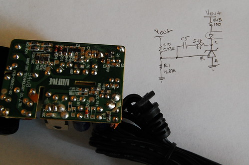
To modify the output circuit, the feedback circuit must be modified. I sketched out the circuit and learned that this particular AC adapter uses a clone of the TL431 reference+error amplifier circuit (which is the weird zener-diode looking thing in the photo above). This particular device, the AM431, has an internal 2.495V reference. The output voltage is divided down so it can be compared with 2.495V, and this is done with a resistive divider formed by R1 (4.87K) and R10 (5.23K). R10 goes to the output voltage, and R1 goes to ground. In this design, I can only modify R1 since R10 (acting in combination with the feedback capacitor) also determines the loop compensation pole (no need to mess with this). Based on my reverse-engineered schematic of the secondary side, the formula for the output voltage is Vout = (1 + R10/R1) * 2.495. Replacing R1 with a 3.3K resistor should bump up the output voltage.

It’s easier to remove a surface mount resistor using two soldering irons, but if you only have one, you can blob a bunch of solder on top of the resistor to wet both sides, and then flick it off with the iron. Be careful to get rid of any splattered solder since it could cause some dangerous short circuits.

You can test it before putting the case back on by plugging it into a power strip that has a circuit breaker and a switch–turn it off first! Connect a multimeter to the outputs with alligator clips, and use one hand to switch on the power and check the voltage. If you want to be a little extra safe you could plug the power strip into a GFI outlet. The safest approach (especially if you want to take measurements on the AC line side of the isolation barrier) is to connect the whole rig to an isolation transformer. Once you’ve confirmed that it works, put the case back together and mark the label with the new output voltage. If the output voltage is higher, you will need to decrease the current rating proportionally. If you’re decreasing the output voltage, you shouldn’t increase the current rating since internal components may have a pretty low maximum current capability.

If you want more information about the TL431 (which is a really neat little device that could be useful for lots of other circuits), check out this application note: Designing with the TL431.
IEE Clock

Clocks, Projects 7 Comments

Update: more photos and information in the followup post.

Wow, things have been very busy lately–I moved to a new apartment, traveled to China, attended my brother’s wedding, and still had time to finish another clock!

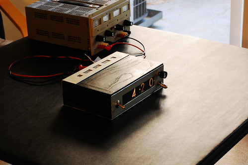
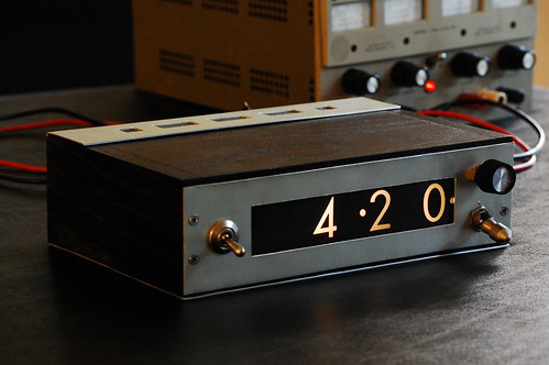
IEE Clock - Front View

This one actually does have filaments. There are 12 light bulbs per digit; one for each numeral, and two for decimal points (left and right). These are neat little display modules that were made by a company called IEE (Industrial Electronic Engineers) way back before 7-segment LEDs were invented. Each light bulb sits behind a clear printed slide with the corresponding number printed on it in negative (the number is clear and the background is black), and in front of the slide is an array of tiny lenses. When a light bulb turns on, it projects an image of the number through the lens and onto the back of the lightly frosted plastic at the front of the display module. The Vintage Technology Association has a great exploded view so you can get a better idea of how this works.

IEE Clock - Front Panel

The clock itself is fairly pedestrian although this design uses a quadrature encoder (the black knob on the upper right) to set the time. Instead of pushing on a button and waiting while the numbers slowly tick by, it’s much easier to just spin a knob.

Keeping time is the function of a DS3231 IC. The display is not multiplexed. A multiplexed display would involve a lot of diodes which would dissipate quite a bit of heat, and for this design, I use 6 ULN2003 driver ICs connected to 2 MAX7300 GPIO expanders. Technically I used devices that are pin compatible with the ULN2003 since nobody seemed to have any in stock. The microprocessor is a PIC18F2420 which communicates with the DS3231 and both MAX7300 devices using I2C.

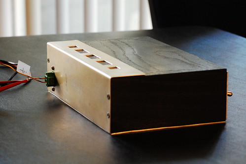
Here is the back of the clock. You can clearly see the vents which allow the heat from the light bulbs to dissipate.

IEE Clock - Rear Panel

This clock will be at Maker Faire, so if you plan to attend, feel free to stop by my booth and take a look in person.

1948 Philco 48-225 Table Radio

Restoration 2 Comments

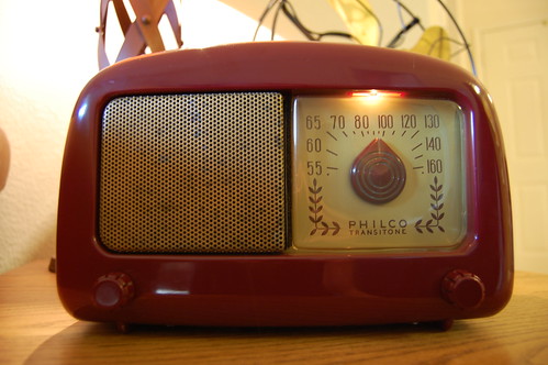
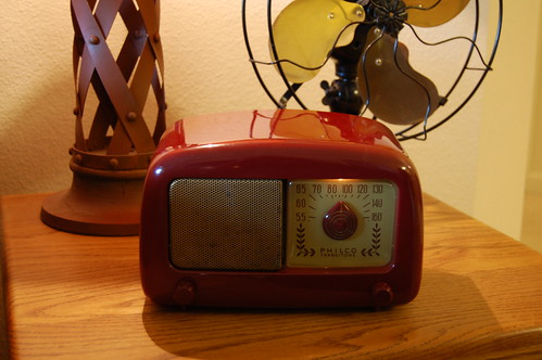
Recently I completed restoring a Philco 48-225 AM tube radio. This radio was produced by Philco in 1948, and it was one of the first radio models to have a plastic (polystyrene) case instead of a bakelite case.

When I received the radio, the case was pretty scratched and banged up, and there was a big crack on the left side. Inside was a lot of dust and bits of dried leaves. Most of the tubes were missing, and the ones that came with it were the wrong type.

The case cleaned up nicely after a lot of wet sanding with fine-grit sandpaper and polishing with Novus 1, 2, and 3. The gold paint on the speaker grill was flaking off, but I decided to leave it alone. I saw a photo of the same model radio on eBay and someone had ruined the grill by trying to polish it–the gold paint is a very thin layer and it came off in patches.

Using superglue I fixed the crack and sanded it so that it’s barely visible. I hear you can also use a solvent-type glue, but I didn’t have any. The superglue repair is probably fragile so I will have to be gentle.

Philco 48-225 - Standing Proud
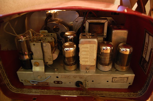
Turning the radio around, you can see the “All-American Five” tube complement. They are the 7A8 converter, the 14A7 IF amplifier, the 14B6 2nd detector/1st audio AVC, the 50L6GT audio output amplifier, and the 35Z5GT rectifier. All the tubes except for the 35Z5GT are of the Loctal variety. Unfortunately the back cover of the radio is missing.
Philco 48-225 - Glows Inside
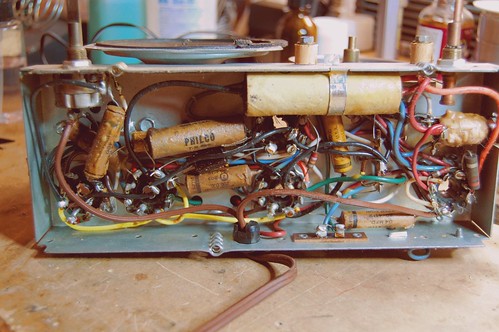
Here is the underside of the chassis before I restored it. You can see how the paper capacitors are coming apart due to age. These radios were designed to be very low cost and were not supposed to last a very long time. The sectional electrolytic capacitor (the long pale tube on the upper right) in particular did not work at all because the electrolyte had seeped out completely.
Philco 48-225 - Innards
I ended up replacing most of the capacitors. For this restoration I pushed the guts out of each capacitor and slipped the new capacitor inside the old one, sealing the ends with wax. This keeps the underside looking authentic.

Notice that there is no power transformer inside this radio. This radio operates directly off the AC line. The filaments for all 5 tubes are wired in series and the voltage ratings add up to the line voltage. The chassis itself is not grounded and it is actually part of the antenna circuit. There is a 150K resistor connecting it to one side of the AC line. The plug is not polarized so it’s quite easy to shock yourself on any exposed metal. It’s not a good idea to plug it straight into a wall socket because of this. If you try to add a 3 conductor line cord with the ground prong connected to the chassis, this will short out the radio’s antenna and the radio won’t work.

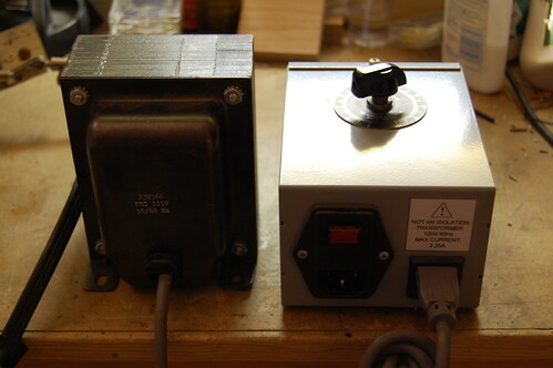
The solution is to use an isolation transformer. I have one connected to a Variac that I use to adjust the line voltage. When I first powered up the radio, I ramped the voltage up slowly to make sure there were no problems along the way. I also measured the line voltage and set it to 115V instead of 120V. AC line voltage was a little lower back in 1948. The difference doesn’t sound like much but running at the higher voltage would apply 6.6V to a tube filament rated at 6.3V. This is enough to reduce the life of the tube.
Variac and Isolation Transformer
With the radio plugged in to the isolation transformer, the radio “floats” relative to the AC line, and it’s safer to touch exposed metal. It’s still a high voltage circuit so the one-hand rule applies. When the radio is isolated like this, it’s also safe to connect it to pieces of test equipment, such as an oscilloscope. The oscilloscope probe ground actually connects to the ground pin on the oscilloscope’s line cord, so if I had tried to test the radio when it was plugged straight in, I could have caused a short circuit that would have melted my scope probe.

It sounds pretty good now and it adds a vintage touch to the living room decor.

Philco 48-225 - Fully Restored

Yes, Still Alive

Projects No Comments

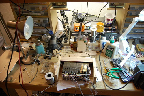
OK, it’s been a while since I’ve posted–a long summer involving friends, BBQs, weddings, hiking, and other social activities. Now that the “cold dark California winter” is setting in, I’m spending more time on projects. Here’s a peek at the latest one.

My messy workbench:
What's This? - Part 2

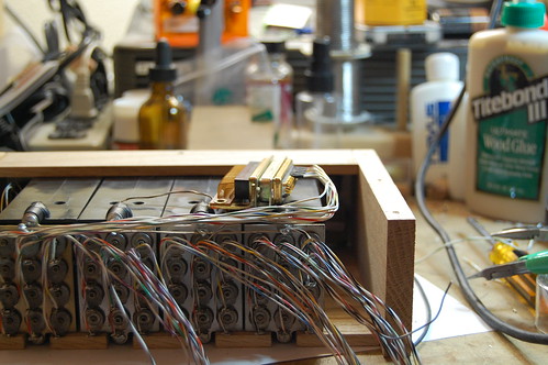
What’s this? It looks like the beginning of a wiring harness.
What's This? - Part 1

Can anyone guess what this is?

2-Axis Joystick From VCR Parts

Projects 7 Comments

One of my CRT clocks has a small joystick on the front which is used to set the time. I built it a while ago using an idler wheel from an old VCR.

Second Scope Clock - Front Panel

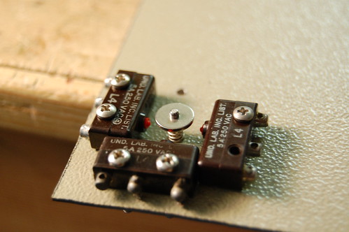
Well, the other day I found another idler wheel from the same VCR, and I decided to share the construction technique so that you can make one too. It’s pretty simple and takes an hour or two. You will need a VCR idler wheel that looks like the one in the picture below, four microswitches (you can scavenge these from an old computer mouse), a spring, and a piece of sheet steel to mount the whole arrangement on. The sheet metal must be steel for reasons I will discuss later.

Joystick - Parts

First, take apart the idler wheel by gripping the top washer with a pair of vise-grips, taking care not too dent it too much. Grab the metal shaft with another pair of pliers and pull the assembly apart. Slide off the screw thread and the metal washer, and take the top washer (which has a convex side and a flat side), and slide it back on to the metal shaft about halfway.

Joystick - Parts Ready to Go

Drill a hole in the sheet metal, and make the hole somewhat larger than the shaft. For my joystick I used a 3/32″ diameter drill. Insert the metal shaft into the hole so that the convex part of the washer faces down against the sheet metal. Turn the piece of sheet metal over and drop a spring over the shaft, then press the remaining metal washer onto the shaft so it captures the spring and tensions it slightly. If you’ve done things correctly, when you push the shaft to the side, it will spring back to the middle. You may need to adjust the spring tension if the shaft doesn’t return all the way. If the shaft can’t move very much in any direction, you’ll need to enlarge the hole.

Joystick - Spring Return Mechanism

In the previous picture, you can see how the convex side of the washer allows the joystick to “roll” against the surface of the sheet metal. When you let go of the shaft, the spring tension pushes the shaft back to the center. The joystick action puts a lot of wear on the sheet metal which is why it’s important to use steel instead of a softer metal like brass or aluminum.

Now it’s time to begin mounting the switches to the sheet metal. You may want to lay them out by hand first just to make sure there is room for them all, and that the actuators end up in the right position. Skip ahead a few photos to see how I arranged my switches.

Joystick - Switch Positioning

Position the switch so that the washer on the reverse side of the sheet metal will hit the actuator just right. You don’t want the washer pushing in too hard–the hole in the sheet metal should stop the shaft from moving to the side rather than the actuator in the switch itself. At this point you may need to adjust the bottom washer so that it lines up with the switch actuator. In my joystick, I had to use a different spring to get the correct tension when the bottom washer was lined up correctly.

When you are finished lining it up, mark the sheet metal where the hole should go (I just dropped a drill bit in the switch’s mounting hole and twirled it between my thumb and forefinger, holding the switch down with my other hand). After you drill the first hole, put a small machine screw into the hole and secure it with a nut on the other side. You can rotate the switch to fine tune its position so the washer hits it in the right place. When it’s dialed in, mark and drill the next hole.

Joystick - One Switch Mounted

In this photo most of the switches are mounted, and you can see that I’ve drilled one mounting hole for the last switch.

Joystick - 3/4 Done

Once the last switch is mounted, take a look at the following photo and make sure that your washer hits every switch actuator correctly.

Joystick - Pushing One Button

At this point I drilled some mounting holes in the corners and took the whole thing apart, and cut the mounting plate out of the larger piece of sheet steel. It’s easier to work with a larger piece of sheet metal when drilling holes and such rather than a tiny piece that is harder to clamp. After putting everything back together, the joystick now looks like this:

Joystick - Completed

The joystick is finished, and it’s ready to be mounted in a front panel. For this joystick, I’ll probably mount it behind a 1/4″ thick piece of oak, so I will drill a big round hole for the joystick shaft and then use wood screws to mount the metal plate to the back of the wood. To dress up the front, I could use a piece of brass pierced with a plus-sign-shaped cutout to cover the hole in the wood like I did on my CRT clock in the first picture. As a finishing touch, I will mount a small wooden knob or perhaps a brass bead on the end of the joystick shaft.

« Previous Entries Next Entries »