CRT Driver Boards, Now With Altium Sources

Uncategorized No Comments

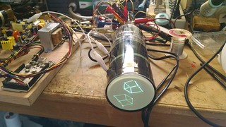
Take a look at my crt-driver GitHub repository. I tidied things up a bit and more importantly, released the Altium project files, schematics, boards, and even the output job file. It’s all licensed under the Creative Commons Attribution-ShareAlike 3.0 license. Read the Creative Commons page for the full terms, but basically you can share or adapt any of it as long as you give me credit (a link to this blog would be appreciated) and make sure that you keep the same license so that others can do the same.

If you don’t have Altium (expensive, closed source), you can at least open and edit the schematics with CircuitMaker (free, closed source, limited). Sadly, CircuitMaker will not let you edit the Altium PCB layout.

Deuterium Arc Lamp

Uncategorized No Comments

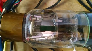
On Saturday I found a deuterium arc lamp at a local surplus store. It was used, and most likely pulled from an ultraviolet spectroscopy machine. I could not find data on the specific lamp model, but I found a similar lamp. On the chance any of you might know what it is, the lamp is marked

D 805 K

56066349

West Germany

H9

Before running any tests with the lamp, I wiped it down with isopropyl alchohol to remove any fingerprint oils. When heated, they can cause the glass envelope to bubble and even melt, destroying it.

To run this lamp, which is a gas-discharge type, you first have to heat up the cathode. There is a very thick double-spiral tungsten filament inside that uses 2V at 4.5A (or 9 watts!). Once it’s warmed up for a minute or two, you apply the high voltage to the anode. I connected it to a current-limited electrophoresis power supply set to 50mA. The lamp started at 350V and settled to an operating voltage of about 84V. Incidentally, the heat generated by this helps keep the cathode hot, and the filament current can be reduced to improve its lifetime.

Here’s a quick video showing what it looks like.

Deuterium is an isotope of hydrogen: hydrogen has one electron and one proton, and deuterium takes that and adds a neutron. It is not a radioactive isotope, unlike tritium, which has two additional neutrons. According to Wikipedia, Deuterium is used in these lamps because it emits more UV with a wavelength less than 400nm.

If you’ve got one of these lamps and you plan to light it up, you’ll need eye protection. I ran it at a very low beam current (most likely it was designed for 300mA!) and the light was not so intense, but you might want more than just a pair of sunglasses if you’re going to full power…

Inside a TTL Logic IC

Uncategorized 2 Comments

Since 2014 is generally considered the 50th anniversary of TTL logic, I thought I’d take a TTL logic chip apart and do a little analysis.

So I started with a DM7438N, lot code M:P9006Y. Looking at National Semiconductor’s device marking convention document, I take this to mean that it was manufactured in week 6 of 1990 at a subcontractor’s fab in the United States and assembled in Malaysia.

The 7438 is a quad 2-input NAND buffer with open-collector outputs. That means the die should look symmetrical to a degree.

To take it apart, I used a rotary tool to carve out the encapsulation material on the top and the bottom, and then picked at it with side cutters until the chip fell out. Sadly I cracked off a corner of the die including one bond pad, but it’s still possible to figure out how it works.

What does all this do? See the image below. I’ve cropped all but one gate and highlighted the various semiconducting regions in different colors. I’ve also given designators to all the components.

Red represents the N-type collector epitaxial diffusion. Cyan represents the P-type base diffusion, and purple represents the N+ emitter region.

The schematic looks like this:

That dual-emitter transistor (Q1) sure looks strange!

How does it work? Well, if both A and B inputs are a logic high, then Q1 is off, but some current flows from R1 (4K ohm) through the base collector junction (since it is, after all, a PN junction) and feeds the base of Q2. Q2 turns on, and its emitter current feeds R3 (1K ohm) and Q3. Q3 turns on as well, and the output Y gets driven low. The non-inverted version of the output signal is available at the collector of Q3 (biased through R2, a 1.6K ohm resistor), but this particular chip doesn’t use it.

If either A or B goes low, then Q1 gets turned on. Current flows through the base emitter junction and the base gets pulled to about 0.6V above ground. No current flows through the base of Q2 because the voltage on the collector of Q1 is just too low for any current to flow. Q3 therefore stays off, and the output Y goes high impedance. By the way, this is what open collector means–the collector of the output stage transistor is left “open” with no corresponding transistor above it to pull it high.

Diodes D1 and D2 are just for input protection.

There are a couple of unused components. There is a resistor right below R1, and another resistor below R2. There are two extra transistors with a shared collector to the left of Q3. A different top metal mask could connect these extra components into the circuit and change the function of the device.

Can you think of some other gates that could be built by changing the top metal mask? Remember that there is only one metal layer which limits where you can route the traces.

XL741 – Discrete Op-Amp

Uncategorized 5 Comments

We’ve done it again! My friends at Evil Mad Scientist Laboratories have a new kit for sale. Following on the success of our Three Fives discrete 555 timer kit, we’ve had a lot of requests for a discrete 741 op-amp.

The XL741 is based on the datasheet schematic of the original uA741 op-amp IC from 1968. You can wire it up in a classic op-amp circuit and probe nodes inside the IC so you can see how the chip works. Play with differential pairs, modify the compensation, and change bias currents to your heart’s content!

Flea Market Find–Dual Gun CRT

Uncategorized 5 Comments

At the electronics flea market on Saturday, I found a 3ABP7 dual gun CRT. This one was built by DuMont, most likely intended for the 3″ version of their 5″ Type 279 Dual Beam Oscilloscope.

So of course I had to fire it up. There are two sets of deflection coils, so I drove them with one deflection board and cross-wired the deflection coils to flip the image around on the second gun.

The guns themselves have a common cathode connection and separate grids, which forces me to drive them both in parallel since my deflection board video amplifier keeps the grid at a constant potential and drives the video onto the cathode.
Dual gun 3ABP2 CRT

Here’s a closer look at the guns. The filaments are connected in parallel so this tube uses twice the normal current.
Dual gun 3ABP2 CRT

« Previous Entries