November 19, 2012
Uncategorized
8 Comments
It’s been quite some time since I last posted about this. The project has been on the back burner for some time now since I’ve just been so busy with other things. It’s actually pretty far along the process but the cost of the parts is just too high, and the kit has quite a few parts.
I’ve been revisiting the design again to see if I can make it easier to build and less costly.
A question: Would you consider a version without a DAC? Instead of having an 8-bit digital interface (Arduino compatible), it would have analog X and Y inputs and a video/blanking input.
November 19, 2012
Uncategorized
No Comments
If the site’s been very slow for you lately, it’s because someone used a PHP injection attack to add some potentially malicious Javascript to the top of the page. It should be fixed now. Thanks to Olli for the tip.
April 28, 2012
Uncategorized
No Comments
Wow, it’s been a few months since my last post. Sorry for the blog silence. I got very busy with a new job and just haven’t had the time to work on projects at all, let alone blog!
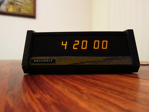
So here’s a quick one–it’s a Heathkit GC-1005 digital clock that uses Panaplex displays (Neon filled). I picked it up at the electronics flea market and it looked like someone had been trying to get it working before me, and they left a bit of a mess. I had to clean up the wiring job and check the electrolytics to make sure they were still good (they were).
The reason it wasn’t working right is that some of the component leads on the bottom of the PC board had poked through a paper insulator and shorted out against the switch contacts on the bottom of the case. All I had to do was trim the component leads and fix the insulator.
May 30, 2011
Uncategorized
14 Comments
At Maker Faire, a lot of people asked me if I had a kit available for any of my CRT clocks. Based on the amount of interest, I’ve decided to put together a kit that will make it easy for people to drive cathode ray tubes using simple digital or low voltage analog control signals. The kit will include a PC board and all the components as well as detailed assembly instructions. For people that opt to use the digital interface, the kit will also include source code libraries making it easy to generate simple vector graphics.
The kit will use surface mount components, but none smaller than 0805. The ICs will be SOIC or SOTs, with the exception of the DAC, which is TSSOP.
Because this would be the very first surface mount kit many people attempt, I’m trying to figure out an approach for the assembly instructions that will make it easy to succeed. Some ideas I’ve had so far are:
- Solder the DAC first since it has a fairly fine pitch package (TSSOP). The kit might include a second DAC as a spare. By soldering it first, it’s easier to check for short circuits and open circuits. Another approach is to make a “spare parts kit” available that has some of the commonly “blown” parts.
- Assemble the kit in sections, testing the circuit a piece at a time. For example, after assembling the DAC, you would assemble the filament power supply and then test it to make sure it works and outputs the proper output voltage. This makes it easy to correct any mistakes as they occur. I don’t want people to assemble the whole board, throw the switch, and not have a working kit–or worse yet, have the kit go up in smoke.
- It makes sense to release the assembly instructions on a site like Instructables, where it’s easy to include detailed macro photos of critical assembly details (like diode orientation). It also makes it easier to correct the instructions for mistakes, and it avoids the environmental impact of including printed instructions with the physical kit.
Hobbyists seem to have an aversion for surface mount components. With a little practice, I’ve found that it’s faster and easier to use surface mount components. Think about all the time you could save by not having to bend and clip resistor leads. You can solder most of the components without having to flip the board over.
If you have any ideas, please feel free to comment. This is all still in the early stages so there is plenty of room to change things and try new approaches.
