January 7, 2009
Cleverness, Projects
21 Comments
In this previous post I disassembled the Coby DP-151SX digital picture frame. This device is very hackable, and includes a lot of goodies such as a Li-Ion battery and battery charger circuit as well as a neat little color LCD display with a white LED backlight. The pinout for the LCD is in the previous post.
The MAXQ2000 microcontroller development board I have uses a 0.1″ spacing header to connect to the I/O pins, so I made a little adapter and wired it up to the LCD connector using wire-wrap wire. It uses 13 I/O lines, but that could be reduced 11 if CS# is wired to ground and RST# tied to a separate reset IC (such as a MAX811). It’s actually a good idea to use CS#, because you can then multiplex the functionality of all the other pins and recover that I/O.
Here is a picture showing the LCD up and running with a simple test pattern:
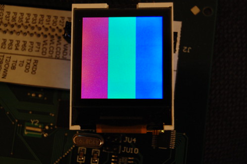
It’s not 128×128, but actually 132×132 pixels. The color depth is 16-bit using a fairly standard 5-6-5 bit encoding. See the PCF8833 datasheet for more details.
Spark Fun has a similar LCD display which uses the same controller, only it costs $20. Amazon.com sells the Coby-151SX in black for $10. Not a bad deal: for $10 less you get a Li-Ion battery, mini-USB cable, and a driver CD, which you could use as a coaster for your Mountain Dew to help with the LCD programming. Spark Fun has some sample code which you should easily be able to adapt for parallel mode (since the Coby LCD connector brings out the parallel data lines, unlike the Spark Fun LCD).
The source code for my test program will get posted once I clean it up and possibly add functionality (Character fonts? Bit blitters?)
January 3, 2009
Projects
1 Comment
Recently I obtained two Coby DP-151SX digital photo keychains to see if it is possible to hack the device. The answer is yes. These devices can be purchased for as low as $9, and I thought they might make a good source of color LCD displays. There is a project to hack small photoframe devices such as these, and they have already developed some tools to hack the firmware and display dynamic images (such as an MP3 player status screen) using the USB connector on the device. The Wiki at the previous link is a good resource.
Below is a photo of the disassembled device. Click the photo to see the Flickr notes annotating different parts of the device.
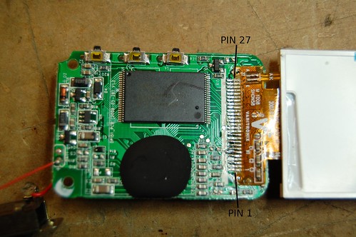
The specs of the device are as follows:
- LCD: Varitronix COG-C147MVGA, 128×128, chip-on-glass (COG) integrated controller with white LED backlight.
- CPU: Possibly the ST2203U 65C02-compatible device with built-in USB engine.
- FLASH: Spansion S29AL008 1Mx8 NAND FLASH memory.
- Battery: 180mAh 3.7V lithium ion rechargeable.
The ST2203U uses a 65C02 processor core with several peripherals: a DMA engine, FLASH memory controller, real-time clock, LCD controller (not used in the Coby device), and a USB engine. It has an onboard mask ROM, but this appears to be disabled on the Coby device. Since resistor R12 is jumpered with a zero-ohm resistor, the ST2203U boots from the external memory. If R13 was jumpered instead, then the device would boot from the internal memory. Apparently the program that comes with the Coby device has the ability to download new firmware through USB. I’m tempted to write my own firmware for this creature, but the lack of an ICE along with a decent toolchain has deterred me.
The device has a built-in battery charger. I have not yet attempted to reverse engineer it yet. The lack of inductors makes me think it’s a linear charge circuit.
The most interesting part, at least to me, is the LCD screen. It has a built-in controller which appears to be similar to or compatible with the PCF8833. Varitronix, of course, does not provide data on this particular LCD display. Based on a little reverse engineering (since many of the control lines are shared with the memory chip) I was able to figure out a pinout:
- VCC (3.0V, but it probably works at 3.3V too)
- GND
- Unknown. Connected to the COG IC but is not driven as an output. This may be the OTP programming control pin.
- NC (but can be connected to the COG IC with a jumper on the flex cable, J1)
- CS# (Chip Select)
- D/C# (Data/Command)
- RD# (Read)
- WR# (Write)
- RST#
- D0
- NC
- D1
- NC
- D2
- NC
- D3
- NC
- D4
- NC
- D5
- NC
- D6
- NC
- D7
- NC
- LED Cathode
- LED Anode
The next step is to detach the LCD and wire it up to a breakout board. Then I can connect the breakout board to a microcontroller and attempt to communicate with it.
December 1, 2008
Cleverness
No Comments
CNET’s Crave has a really fascinating post about a gentleman in Vietnam who has figured out how to unlock 3G iPhones–as of this writing, there is no software way to unlock this phone.
Unlocking iPhone 3Gs–the Vietnamese way
There are some interesting pictures showing some methods used by the Vietnamese technicians to remove and replace the flash memory device. They use a cheap hardware store heat gun, which is normally used to strip paint, to heat the solder until it melts, and then they remove it with tweezers. One of the problems with this sort of rework is that the adjacent components often loosen and shift or even fly off completely.
Look at the last picture in the article. The technician is using some small metal plates to protect the other components from the blast of hot air. Genius!
November 8, 2008
Restoration
No Comments
My Wagner fan restoration has progressed well (see previous posts). Recently I finished the final assembly. I took the entire fan apart and cleaned every part. Many of the parts needed to be repainted, and the fan blade needed to be stripped of the paint and polished.
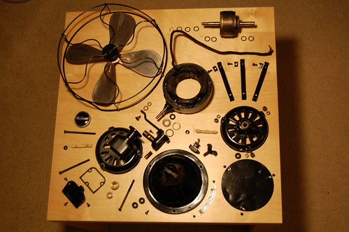
Here are all the pieces laid out. Please click on the photo for detailed Flickr annotations. brittnybadger has taken some really great photos of household appliances in similar “poses.” I wish my photo was as good as one of hers.
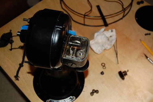
The oscillator gearbox looks really interesting. Here it is before I added gearbox grease. It takes the high speed rotation of the fan motor and slows it down using two worm gears, and then drives the crank which rotates the fan from side to side.
There is still some work left to be done. The fan blade is made of steel which was copper plated before being painted. Time has not been kind to the plating. When I stripped the paint, I could see green corrosion and pitting that ruined the plating, so I had little choice but to polish off the rest of the copper plating. I have not yet decided whether to leave the blade steel or to get it copper plated again. Regardless of that I like the look of an unpainted blade.
The headwire which connects the fan motor to the base and the switch also needs to be replaced. The rubber insulation underneath the cloth has gotten brittle and cracked. Similarly, the line cord is not original and I need to do some more research to find out what an original line cord looks like.
Finally, I need to make some safety upgrades. I have already added a fuse in the base that will prevent shorts in the motor windings from causing a fire. I still need to add a grounding wire since the case is metal and could shock people if one of the motor windings touches it.
November 8, 2008
Restoration
No Comments
During the restoration process of my antique Wagner fan, I found that the bearings are a lot different than the Emerson 28646 I restored. This particular fan has a bearing on the front and one on the rear of the motor housing, and each bearing has an oil sump, some small holes to allow the oil leaking from the front and rear of the bearing to trickle down into the sump, and a wool wick that uses capillary action to “pump” oil out of the sump and bring it back up onto the bearing surface. Here’s a picture that shows how it all works:
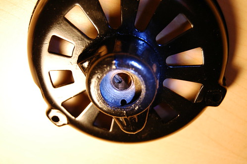
In the picture, the oil sump is the lump protruding from the bottom of the round bearing housing. You can see the small hole that allows oil to drain back into the sump. On the inside of the bearing, there is an ovoid hole that lets the wool wick contact the rotating shaft and apply oil sucked up from the sump. You can click on the picture to see the Flickr annotations. Here is what the wool wick looks like:
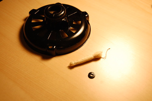
The small round washer acts as a plug to keep the wool wick inside the bearing, and the hole is where you add oil. The wick itself is made of several strands of worsted wool yarn that have been tied with string. Originally this was a black lump of grease when I first pulled it out of the bearing, but I was able to clean it up by soaking it in laundry detergent. A greasy oil wick prevents it from working, and my Wagner’s front bearing was bone dry when I first took it apart. If you’re doing a restoration and you need to replace the wick, you must use real wool. Synthetic fibers apparently do not have same degree of capillary action. Wool wicking is also the material of choice for steam locomotive bearings.
The wick fits in the hole on the top of the bearing.
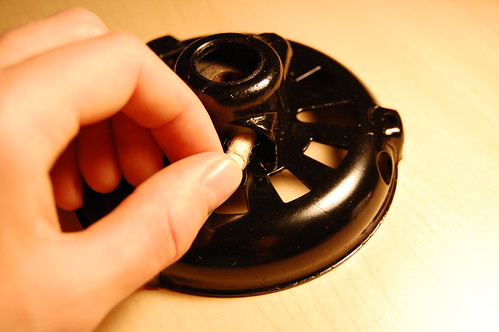
Here is a photo showing the assembled bearing (minus the washer).
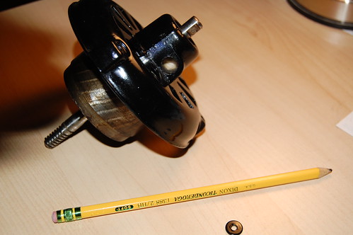
I used a pencil to pack the wick into the bearing. It is now ready for oiling. I am using the 3-in-1 SAE 20 oil that is meant specifically for motors. It does not smell so strongly as the multipurpose 3-in-1 oil. In this picture below, you can see the wick soaked with oil on the fan after final assembly:
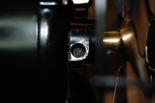
Add oil about 10 drops at a time and allow it to soak in for an hour. Do this again until the part of the wick you can see is saturated. If you add too much oil then it could spill out of the top, so you don’t want to add more oil than the wick can hold. It’s important to make sure the wick never goes dry so that your bearing will always be properly oiled.
