A New Fan

Restoration 1 Comment

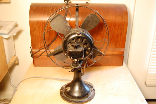
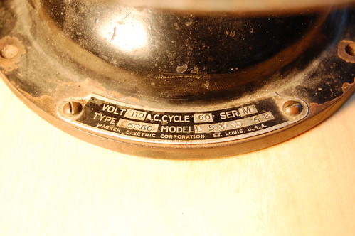
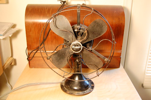
At the electronics flea market, I found another antique desk fan. This one is a Wagner 9″ oscillator, series M, model 5260, model L53A68. I am not certain when it was manufactured: my guess is the early 1940s.
Wagner Antique Fan
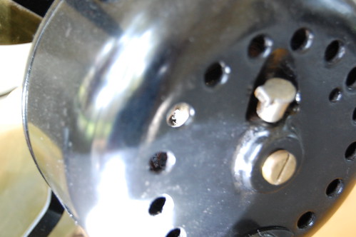
On the rear of the fan you can see the oscillator gearbox:
Wagner Antique Fan
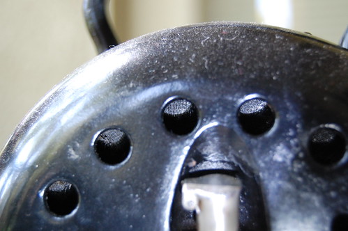
Here is a closeup of the fan’s nameplate. It has everything except for the date of manufacture.
Wagner Antique Fan
This fan is in reasonably good condition, compared to the Emerson that I restored before. There is very little rust which makes the restoration job much, much easier.

Panaplex Wall Clock

Clocks 7 Comments

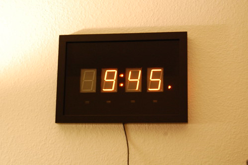
Here are some photos of my latest clock. It uses large Panaplex-style neon-filled displays. I do not know the part numbers or the brand: these appear to be factory rejects, and each of the digits appears not to meet mechanical tolerances.
Panaplex Clock - Completed

Under each digit is a reed switch that you can trigger using a magnet to change the number of that digit. The circuit board sits behind a regular picture frame where the glass has been painted black from behind. I masked off rectangular regions to allow the displays to show through, and I hand painted the “P” for the PM indication.

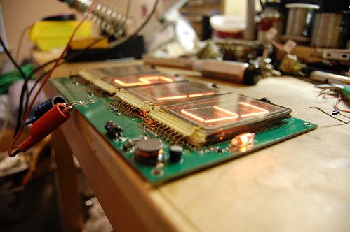
This is what the circuit board looks like:
Panaplex Clock - PCB
The 180V power supply is on the lower right of the circuit board. The microcontroller timekeeping circuit is located underneath the leftmost digit. It is a PIC18F2420. I am using the onboard 32KHz oscillator with an external watch crystal, but I left room for a DS3231 timekeeping chip. It supports a battery backup, and you can see the place where it would go on the board right underneath the hour digits.

The left edge of the board has a row of header pins that I use to check the voltages, program the PIC in circuit, and probe the cathode voltages with a scope. The neon numerals have very interesting electrical characteristics, and eventually I will post an article about that.

Panaplex displays must be multiplexed to prevent damage. They are slightly more finicky than Nixie tubes, but the driving circuit is quite similar. I had to add a set of clamping diodes to limit the voltage swing on the cathodes (each segment is a single cathode).

This design was very fast and straightforward. I spent two evenings prototyping the circuit and getting the multiplexing working, another two evenings to enter the schematic and lay out the PC board, and two days to assemble, test, and finish the clock software.

Panaplex Clock - PCB

Emerson Fan Blade Removal

Restoration 10 Comments

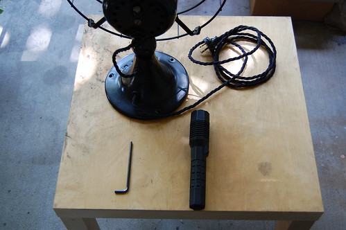
So you’ve obtained an antique desk fan, and you want clean it up and restore it, but you just can’t seem to figure out how to get the blades off. Based on a number of email inquiries, here are instructions for removing the blades from certain Emerson antique desk fans. You will need some basic tools, including an Allen wrench, a flashlight, and a wrench appropriate to removing the cage.
Emerson Blade Removal, Part 1
Before you begin, you’ll need to remove the cage so you have easy access to the fan blades. Usually that means you need to undo the four bolts holding the cage assembly to the front of the motor casing.
Next, you need to examine the rotor of your Emerson’s motor using a flashlight. Look for a “blind” hole drilled into the side of the rotor. These are drilled by the manufacturer to remove some metal and balance the motor.
Emerson Blade Removal, Part 2
Once you’ve found the hole, insert the Allen wrench through one of the vent holes in the motor casing and into the balancing hole on the rotor.
Emerson Blade Removal, Part 3
The next photo shows a closeup of the Allen wrench inserted into the balancing hole.
Emerson Blade Removal, Part 4
When you do this, be very careful not to damage any of the stator windings. They are very fragile and protected only with a layer of cloth tape.
Emerson Stator Windings
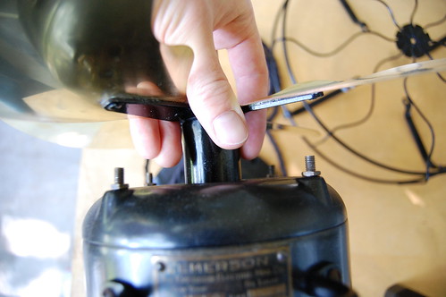
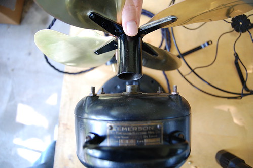
Once you’ve got the Allen wrench in position, grasp the fan blade by the blade hub (commonly called the “spider”). Yes, the blades will provide more leverage, but they bend pretty easily, and once you’ve bent a fan blade, it will never be the same again.
Emerson Blade Removal, Part 5
The threads fastening the wheel hub to the rotor are left-handed, so you need to spin the hub clockwise to unscrew it. The hub on my fan had frozen onto the rotor, and no amount of physical force would get it turning. I trickled some penetrating oil down the hub so it could get into the threads and free things up, but even after that I had to heat up the hub spindle with a heat gun. The heated metal expanded and broke the threads loose. It made a terrible squealing noise when I unscrewed it.
Emerson Blade Removal, Part 6
And the blades are off! You’ll want to clean up the threads at this point to remove any crud or rust, and add some oil to make it easy to remove the blades next time.

Electronics Flea Market Finds

Uncategorized No Comments

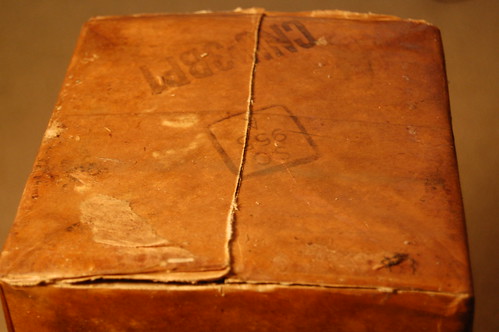
Yesterday I went to the local electronics flea market and picked up some interesting items. The first is a 3BP1 3″ round cathode ray tube. It was in the original box which was still sealed and coated with wax.
3BP1 Cathode Ray Tube
The label indicated that the tube was manufactured in 1945.
3BP1 Cathode Ray Tube
Of course I needed to open it to make sure the tube was intact. Many times these tubes are stored upside down, and often fragments of various internal parts will break off due to vibration, fall down, and ruin the phosphor screen.
3BP1 Cathode Ray Tube
I half-expected an Indiana-Jones-style puff of ancient air as I broke the seal.
3BP1 Cathode Ray Tube
And yes, it’s in perfect condition. The outside of the tube is slightly dirty but these tubes really didn’t need to be cleaned before leaving the assembly line to work properly.

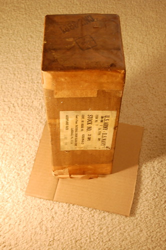
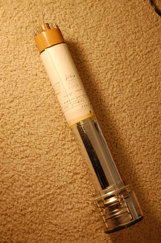
The next find is an RCA 5820 Image Orthicon tube. This tube came in the original box which indicates that it was shipped to KGO-TV in San Francisco in 1953. It would have been used in the RCA TK-11 TV camera which was very common at the time.
RCA 5820 Image Orthicon
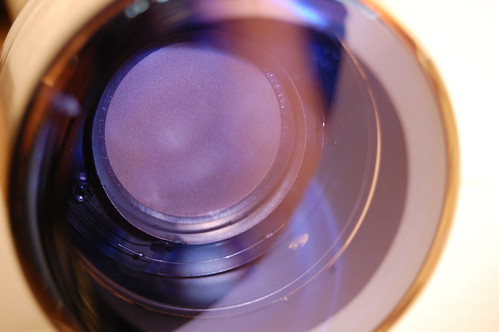
This is a closeup of the front.
RCA 5820 Image Orthicon
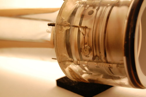
And here you can see the internal elements. The round bit in the middle is actually a very fine mesh screen.
RCA 5820 Image Orthicon

Laser Printer Scanning Mirror Experiments

Projects 18 Comments

Digging through my junk box today, I unearthed the scanning mirror from a laser printer, otherwise known as the Heart of the LaserJet. It’s got the infrared laser that generates the image as well as the scanning mirror that creates the raster. It’d be fun to get it up and running for nefarious purposes…
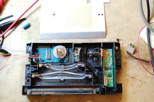
Laser Printer Scanning Mirror Assembly
The scanning mirror and motor uses a “custom” (undocumented) Panasonic motor driver, the AN8247SB. As usual, Google returns a million hits for grey market parts brokers who spam the keywords with things like “PDF” and “datasheet” without offering any actual information.
So my usual plan of attack does not succeed.

The second step is to examine the single 5-pin connector to see what I could figure out. Pin 3 is obviously ground because it is the only pin connecting to any large ground planes. What I suspect to be pin 5 appears to be the power supply since it connects to two very low valued resistors (0.75 total) which probably perform a current sense function. Most of the other pins disappear inside the undocumented chip.

Digging around in my junk box produced the power supply board for the laser printer. I was able to find the other side of the connector and quickly verify that pin 3 is indeed ground. What I thought was pin 5 is actually pin 1, and it is indeed power. Tracing back through the power board I notice that it connects to a filter capacitor with a 25V rating. Based on that I conclude that it is very likely a 12V rail. I soldered some jumper wires onto the board and began experimentation in earnest.
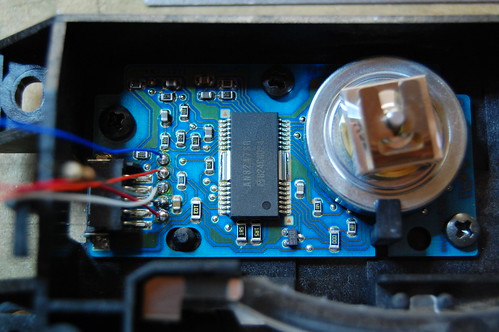
Laser Printer Scanning Motor
Connecting the board to 5V didn’t result in any excessive current, so I slowly ramped up the voltage to 12V. Nothing happened. Not even anything bad.

Looking carefully at the laser printer’s power supply board, I traced the other three connections. They all went into a big microcontroller, but the wiring connections were different. Pin 2 had a 10K pullup to some low voltage supply, pin 4 went straight into the microcontroller, and pin 5 came from an RC filter from the microcontroller.

First I tried connecting a 10K pullup resistor to pin 2 on the motor driver board to 3.3V, and I hung a scope probe on it. It was a logic low. I spun the mirror assembly, and I saw pulses! This must be the tach output. By rotating the mirror very slowly by hand, I counted 6 pulses per revolution.

Next I probed the voltage on the other two pins, which were both weakly pulled up to about 3.6V on the motor driver board. I pulled pin 4 low, and the tiny mirror spun up with a whine to about 13,000 RPM (as measured by the tach output)!

That was really great because I was worried that those two pins were I2C control lines which would have made reverse engineering a lot more difficult. It’s not impossible because you can hook it up to a microcontroller and scan all possible I2C address to see if any slave devices respond, then randomly try to access registers… It gets pretty messy anyway.

The last pin gave me a bit of a headache because grounding it didn’t really do anything. I tried grounding it through an ammeter and noticed that the current, although it started at a few hundred microamps, tapered off quite rapidly. There must be a capacitor in series somewhere on the motor board, and that means the pin is designed for AC signals. Since no signal came out of the pin, it must be an input. I connected a function generator at a few kilohertz with a 3.3Vp-p square wave, and when I turned on the motor, I noticed that it “cogged” a lot and generally had a hard time. On impulse, I dramatically increased the frequency. Suddenly the motor slowed down and settled at a constant speed. By changing the frequency, I could manipulate the motor speed.

So pin 5 is a synchronization input. I guess the RC filter on the microcontroller side was designed to help reduce EMI in the cable. The next step was to figure out the relationship of input frequency to output speed, so I connected my trusty old Nixie frequency counter to the output of my function generator and my multimeter (set to frequency) to the tach output. The ratio appears to be fixed: divide the input frequency by 136.6 and you’ll arrive at the RPM of the mirror.

Here’s the complete pinout:

1 – +12V
2 – Tach output (open drain, 6 pulses per revolution)
3 – Ground
4 – Enable (active low, so drive it low to turn on the motor)
5 – Synchronization input

Now it’s time to come up with projects…

Just to give you a hint, I have something in mind involving a photomultiplier tube.

Drop me a line in the comments if you think you can guess what my idea is, or to post your own ideas, or even if you find this information useful for your own project.

« Previous Entries Next Entries »