Maker Faire 2011
May 19, 2011 Uncategorized No CommentsThe Maker Faire is a neat DIY convention that happens every year. I’m bringing some of my projects to the Maker Faire Bay Area; just look for Tube Time. Come and say hello!

The Maker Faire is a neat DIY convention that happens every year. I’m bringing some of my projects to the Maker Faire Bay Area; just look for Tube Time. Come and say hello!
Watch this YouTube video, and then read the rest of the post.
So how did I do it? It is actually a very simple circuit.
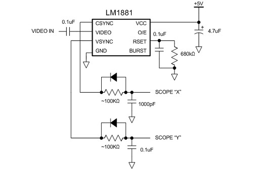
The LM1881 separates the sync signals from the NTSC composite video coming from the camera. It outputs a vertical sync signal (active low) that asserts during the vertical retrace period and a composite sync signal (also active low) that asserts during the horizontal retrace period and also during the vertical retrace period (but with a set of serration and equalization pulses).
To connect these to my oscilloscope, I have to use the XY mode on the scope and convert the sync signals into deflection signals. This is done using analog ramp generators. The simplest way is to use an RC circuit to generate a rather nonlinear ramp. When the sync signal goes high, it charges the capacitor through the resistor. When the sync signal goes low, the diode allows the capacitor to discharge immediately. This generates the sawtooth waveform. Adjust the R value so you get the most complete ramp (goes most of the way up to 5V).
The video signal is fed directly into the Z-axis signal at the back of the scope. Because the Z-axis signal has the opposite polarity from regular video (it is a blanking signal, where a positive voltage will turn the beam off), I had to build a really basic video buffer to invert the signal. This is a nice exercise in transistor biasing using four external resistors. Don’t ask me for the schematic–you should try to build it yourself. Even if you don’t get it working properly right away, you’ll discover all sorts of interesting analog video effects!
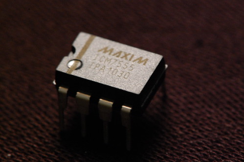
Yes, it’s not really vacuum tube related, but I built an entry for the 555 timer contest. It uses an ICM7555, which is Maxim’s second source of Intersil’s CMOS version of Signetic’s original NE555 timer. Turns out the fact that it is CMOS is important for this particular circuit…
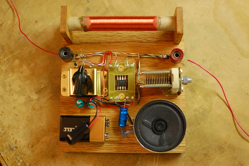
My entry is an AM radio. The only active device (silicon, germanium, or otherwise) is the ICM7555. The tuning is accomplished with an inductor and a capacitor, and the ICM7555 acts as an AM demodulator and class-D power amplifier to drive the speaker.
You may be wondering how all this is accomplished with a 555. The schematic is below.
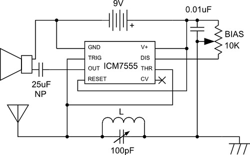
Here’s how the circuit works: The AM radio signal is tuned by inductor L, which is 300 turns of wire on a 1/2 inch diameter cardboard tube made out of an old toilet paper roll, along with the 100pF variable capacitor. One end of the parallel configuration of L and C connects to an antenna (surprisingly long!) and the other end connects to a ground wire which is tied to the AC outlet ground (old books tell you to ground it to a water pipe). So far this is exactly like an AM crystal radio.
The 555 timer is configured as a pulse width modulator in a non-traditional configuration. If I used the standard approach and connected the input to the CV pin, the low impedance of the pin would prevent the circuit from receiving any radio signals. I had to invert the circuit and tie both high impedance analog pins, Threshold and Trigger to the radio signal input. This is the reason why the CMOS version of the 555 timer performs much better than the standard bipolar, which has higher input bias current.
The pulse width modulator ramp is created by the 0.01uF capacitor and the 10K bias potentiometer which are connected to the Discharge pin. The potentiometer wiper goes to the LC arrangement. With no radio signal coming in, the voltage on Threshold/Trigger ramps up until it hits the threshold, and then Discharge causes the voltage to ramp down again.
When a radio signal comes in, it gets superimposed on the ramp signal, causing the threshold and trigger comparators to trip early or late in a cycle. This variation causes the output duty cycle to vary, which we can hear as sound in the speaker.
Demodulating the signal properly requires adjustment of the bias knob, so that part of the radio signal is “clipped” and ignored by either the threshold or trigger comparators. This ensures that the negative “halves” of the radio wave don’t cancel out the positive “halves”.
Want to hear what it sounds like? Check out the video below:
And of course, I can’t end the post without a gratuitous shot of the ICM7555 in circuit.

My friend Jeri Ellsworth recently figured out how to make a point contact transistor by cracking open a germanium diode. It looked pretty straightforward so (deviating from this blog’s usual content) I took a crack at it myself:

The original diode contact serves as the emitter connection. The base is the chip of germanium that is visible in the bottom part of the diode (with the stripe). The collector is a piece of phosphor bronze wire I pulled off the end of a guitar string. I sharpened it to a point with a Dremel sanding wheel and soldered it to a piece of bare wire to make it easier to handle.
The fine-pitched screws are used to maneuver the wires into contact with the block of germanium.
The germanium base is actually n-doped. To create the collector junction, you have to create p-doped regions. One crude way to do this is to apply a burst of current across the reverse-biased junction (positive voltage to base, negative voltage to collector). I don’t know if the mechanism is thermal or electrical, but phosphorus from the phosphor bronze wire gets carried into the germanium, creating the p-type region. For this experiment I used about 200V on a 10uF capacitor, and I discharged it into the junction through a 1K resistor. Jeri originally used something like 20V but I read in a paper several hundred volts were usually used for this purpose.
Jeri used an oscillator circuit to test her transistor, but I got lazy and just put it in a simple inverting amplifier circuit. At first the transistor didn’t work (output was in phase with the input) but after some tweaking of the wires, the output finally went 180 degrees out of phase. This is an absolutely terrible transistor, and the gain is really too low to consider this a transistor.
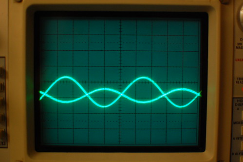
I’m going to play around with it a bit more to see if I can improve the gain…
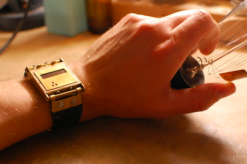
Is that…?
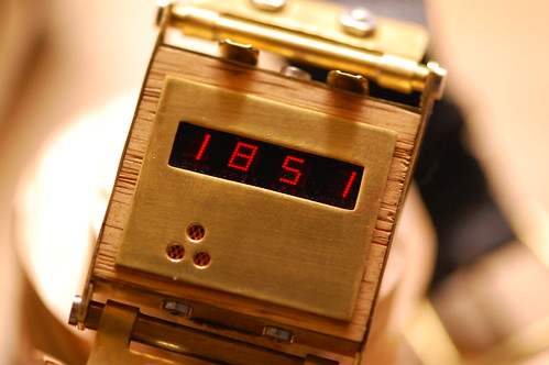
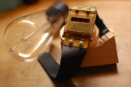
Yes, it’s an LED steampunk wristwatch! It uses the LED wristwatch board (see this previous post). The watch is constructed from a small piece of oak and pieces of brass sheet and tubing. I used hand tools, a Dremel tool and a cordless drill to shape and form each of the pieces.
There are four more LED wristwatch boards left. I wonder what style of watch I should make next…
Here’s one more picture.