If you follow me on Twitter, you’ve probably seen the picture of a CRT deflection yoke undergoing surgery. Well, it’s now installed in a mini Battlezone arcade cabinet that I built for Maker Faire this year.
It uses a 5-inch B&W CRT taken from a broken security camera monitor. I had to rewind the yoke to make the vertical windings fast enough to handle vector graphics. The horizontal windings were already pretty close, but they did need to be rewired to operate in series to reduce the drive current.
The CRT is a bit different than most of the old-style CRTs I work with. For the curious, it uses an EIA E7-91 style base which has an additional grid for acceleration purposes. The lower circuit board in the photo is a potentiometer resistor divider that develops a ~300V bias voltage to drive this additional grid. The upper board is a Cockcroft-Walton multiplier circuit to step up the 1KV power supply voltage to the 4KV necessary for the post-deflection acceleration (PDA) anode. I’m running this CRT a bit under voltage, and it works fine because I’m not trying to fill the whole screen with a solid raster.
The metal enclosure houses the power supplies–it is made out of soft steel with the idea of containing the stray magnetic fields generated by the power supply switching inductors. It works a bit, but I’ve had better luck in the past with mu-metal shields around the CRTs themselves. There are three power supplies: one steps 120V down to +12V, +5V, and -12V. Another steps +12V to +1KV, and the final one steps +12V up to +60V. These last two power supplies are detailed here. They are open-source hardware so you can build your own.
Outside the shield you can see the video amplifier board at the lower left, which is the same circuit used on my electrostatic deflection board but without the deflection amplifiers. At the bottom right is my new magnetic deflection amplifier board which drives the deflection yoke. It is based around an LM4765 audio amplifier IC. I’m not totally happy with the design but eventually I will release the board design. The green board in the upper middle is an STM32F4 Discovery board. The board to the right of it is an audio amplifier that drives the speaker.
The joysticks I machined out of small aluminum blocks. It took some experimenting to figure out how to arrange the springs to get the joystick to return to the center position. The joystick handle on the right is hollow to allow the wires for the fire button to pass through.
I also build a second unit with the same driving circuit but a different CRT–a 5-inch round 5AXP4. This CRT would originally have been used by a TV technician to look for problems with the chassis or the full size picture tube in a customer’s set. The glass is extra thick because the tube was designed to be handled more. This is the same tube that I started experimenting with last year.
Richard built up some of my CRT driver boards and put them to use, testing a variety of CRTs with interesting characteristics, such as the rare 1DP11 or the vintage RCA 913.
He’s also got a nice video as well:
If you plan to build up the CRT boards, I highly recommend you visit Richard’s page. He’s drawn up an excellent connection diagram that shows how to interconnect the HV power board, the video power board, and the deflection/video amplifier board.
On Saturday I found a deuterium arc lamp at a local surplus store. It was used, and most likely pulled from an ultraviolet spectroscopy machine. I could not find data on the specific lamp model, but I found a similar lamp. On the chance any of you might know what it is, the lamp is marked
D 805 K
56066349
West Germany
H9
Before running any tests with the lamp, I wiped it down with isopropyl alchohol to remove any fingerprint oils. When heated, they can cause the glass envelope to bubble and even melt, destroying it.
To run this lamp, which is a gas-discharge type, you first have to heat up the cathode. There is a very thick double-spiral tungsten filament inside that uses 2V at 4.5A (or 9 watts!). Once it’s warmed up for a minute or two, you apply the high voltage to the anode. I connected it to a current-limited electrophoresis power supply set to 50mA. The lamp started at 350V and settled to an operating voltage of about 84V. Incidentally, the heat generated by this helps keep the cathode hot, and the filament current can be reduced to improve its lifetime.
Here’s a quick video showing what it looks like.
Deuterium is an isotope of hydrogen: hydrogen has one electron and one proton, and deuterium takes that and adds a neutron. It is not a radioactive isotope, unlike tritium, which has two additional neutrons. According to Wikipedia, Deuterium is used in these lamps because it emits more UV with a wavelength less than 400nm.
If you’ve got one of these lamps and you plan to light it up, you’ll need eye protection. I ran it at a very low beam current (most likely it was designed for 300mA!) and the light was not so intense, but you might want more than just a pair of sunglasses if you’re going to full power…
A coil saturates when the magnetic field (the B field) has reached the maximum that the magnetic core material can support: if the current (which is what creates the magnetizing H field) increases more, the magnetic field increases very little. The inductance, which is proportional to (B ÷ H), rapidly drops off, causing the current in the coil to increase at a much faster rate. Royer’s design detects this current spike and uses it to switch the transistors (2N74s, in his original paper) into their opposite state.
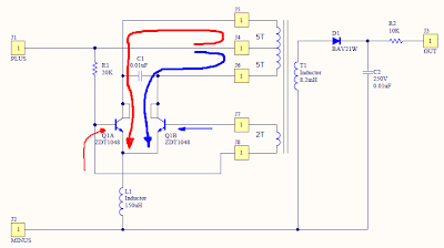
My circuit is a more common LC resonant converter. There are two transistors, Q1A and Q1B. Resistor R1 provides the bias current for the transistors and gets things started. Current (represented by the large red arrow) flows through the center tap of the coil T1 out to Q1A through its collector. The current in the upper half of coil creates a magnetic field, and the magnetic field induces a voltage in the feedback coil. This voltage reduces the base drive for Q1A and increases the base drive for Q1B (represented by the small blue arrow). When that happens, Q1A shuts off and Q1B turns on. The current in Q1B’s collector (represented by the large blue arrow) creates a magnetic field of the opposite polarity in the coil, and therefore causes the feedback winding voltage to reverse polarity (see the small red arrow), turning off Q1B and turning on Q1A. The cycle repeats as long as there is power.
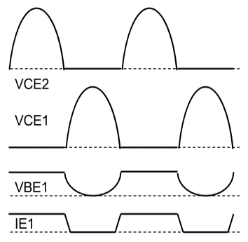
Above are some approximate waveforms. You can see that the transistors go back and forth, driving the coil first one way and then another. Capacitor C1 and inductor L1 help determine the resonant frequency of the circuit. If you measure the voltage across the entire coil, you’ll see a sine wave.
The output winding of the coil has a lot more turns than the input winding, and it increases the voltage (at the expense of the current) dramatically. This high voltage AC goes through the half wave rectifier formed by D1 and gets filtered to DC by C2. R3 limits the current into the Nixie tube.
You might be wondering why T1 is actually an inductor–an 8.2 millihenry one. It just makes the project easier to build. You only have to wind 12 turns on an off-the-shelf part instead of buying a hard-to-find transformer core and adding all the windings yourself.
If you feel so inclined, try adjusting the component values. Start with C1 and then maybe R1 or even L1. Try changing the number of turns on the coil.
Update 11/3/2014: Fixed the coil connections on the schematic, along with the inductance. Also, check out this post to see how the circuit works.
This project has been a long time in progress. It started years ago at a Maker Faire where I built a Nixie tube pendant powered by a lithium coin cell battery. Since then, I’ve decided to make a PC board and put together some instructions on how to build such a power supply yourself. These little supplies are great for steampunk jewelry or possibly single-digit Nixie tube clocks (they’re not quite strong enough to drive multiple tubes). The battery life should be around 3 hours or so for a CR2032 lithium coin cell.
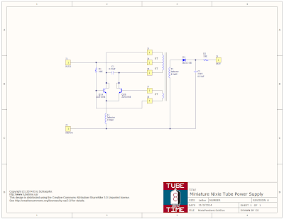
The schematic is below–click for a larger view. The bill of materials is located here, including Mouser Electronics part numbers. If you decide to order, get at least 5 of each part just in case you lose or burn up some of them. Note: Mouser seems to be out of stock for the T1 inductor, but Digikey has it here.
Q1 is a single device; it actually contains two transistors which is why it looks like that on the schematic.
To make it easier to build, I’ve put up a convenient OSH Park project page link so you can order boards. When I ordered from them, it cost $2.80 for a set of three boards (with free USPS shipping). Not a bad deal at all!
When you have boards and components, there’s a specific order of assembly that makes things a bit easier. See this YouTube video:
Basically you need to assemble the components in the following order:
Solder C1.
Solder Q1. Be sure you line up the beveled edge with the extra-wide silkscreen. If you put it in backwards the power supply will not work.
Flip the board over.
Solder D1, then R2, and then C2. C2 is 0.01uF, similar to C1, but it has a 250V rating. It is very important not to mix these up.
Solder R1, and then T1 (the big coil, not marked on the silkscreen).
Take a piece of 32 gauge magnet wire that is 13 inches long and tin about 1/8 of an inch at one end. I use a soldering iron to burn off the varnish. Solder it into the upper left through hole that is below the coil.
Wrap 5 turns clockwise around the coil T1. Thread the end of the wire into the middle through hole below the coil.
Turn the wire around and thread it back through the same hole, pulling it tight to form a tiny loop. Solder the loop to the through hole.
Take the wire and wrap another 5 turns clockwise around the coil. Thread the end through the top right through hole below the coil, and solder it in place. Trim off any excess.
Get another piece of 32 gauge magnet wire that is 5 inches long, and tin about 1/8 of an inch at one end. Solder it into the lower left hole that is below the coil.
Wrap 2 turns clockwise around the coil T1. Thread the end of the wire through the lower right through hole that is below the coil. Solder it, and then trim off any excess
Solder the inductor L1. The reason it needs to be soldered last is that it makes it hard to wind wire around the coil T1.
Solder connecting leads to the +, -, and OUT terminals.
To use it, connect a coin cell’s negative terminal to “-,” the coin cell positive to “+,” and “OUT” to the anode of a Nixie tube. The Nixie tube cathode goes to the coin cell negative terminal. Don’t touch the “OUT” terminal–you could get a shock. In fact, if you build the power supply into jewelry or something people will be touching, insulate all the connections.